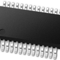
PIC24FJ32GA102-E/SS Microchip Technology, PIC24FJ32GA102-E/SS Datasheet - Page 193

PIC24FJ32GA102-E/SS
Manufacturer Part Number
PIC24FJ32GA102-E/SS
Description
16-bit, 16 MIPS, 32KB Flash, 8KB RAM, Nanowatt XLP 28 SSOP .209in TUBE
Manufacturer
Microchip Technology
Series
PIC® XLP™ 24Fr
Datasheet
1.PIC24FJ32GA102-ISP.pdf
(308 pages)
Specifications of PIC24FJ32GA102-E/SS
Processor Series
PIC24
Core
PIC24F
Data Bus Width
16 bit
Program Memory Type
Flash
Program Memory Size
32 KB
Data Ram Size
8192 B
Interface Type
I2C, SPI, UART
Maximum Clock Frequency
32 MHz
Number Of Programmable I/os
21
Number Of Timers
5
Operating Supply Voltage
2 V to 3.6 V
Maximum Operating Temperature
+ 125 C
Mounting Style
SMD/SMT
Package / Case
SSOP-28
Development Tools By Supplier
MPLAB Integrated Development Environment
Minimum Operating Temperature
- 40 C
Operating Temperature Range
- 40 C to + 125 C
Supply Current (max)
300 mA
Core Processor
PIC
Core Size
16-Bit
Speed
32MHz
Connectivity
I²C, IrDA, SPI, UART/USART
Peripherals
Brown-out Detect/Reset, LVD, POR, PWM, WDT
Number Of I /o
21
Eeprom Size
-
Ram Size
8K x 8
Voltage - Supply (vcc/vdd)
2 V ~ 3.6 V
Data Converters
A/D 10x10b
Oscillator Type
Internal
Operating Temperature
-40°C ~ 125°C
Lead Free Status / Rohs Status
Details
- Current page: 193 of 308
- Download datasheet (3Mb)
REGISTER 18-1:
2010 Microchip Technology Inc.
bit 2
bit 1
bit 0
Note 1:
2:
PMA<10:2> bits are not available on 28-pin devices.
These bits have no effect when their corresponding pins are used as address lines.
BEP: Byte Enable Polarity bit
1 = Byte enable active-high (PMBE)
0 = Byte enable active-low (PMBE)
WRSP: Write Strobe Polarity bit
For Slave modes and Master Mode 2 (PMMODE<9:8> = 00,01,10):
1 = Write strobe active-high (PMWR)
0 = Write strobe active-low (PMWR)
For Master Mode 1 (PMMODE<9:8> = 11):
1 = Enable strobe active-high (PMENB)
0 = Enable strobe active-low (PMENB)
RDSP: Read Strobe Polarity bit
For Slave modes and Master Mode 2 (PMMODE<9:8> = 00,01,10):
1 = Read strobe active-high (PMRD)
0 = Read strobe active-low (PMRD)
For Master Mode 1 (PMMODE<9:8> = 11):
1 = Read/write strobe active-high (PMRD/PMWR)
0 = Read/write strobe active-low (PMRD/PMWR)
PMCON: PARALLEL PORT CONTROL REGISTER (CONTINUED)
PIC24FJ64GA104 FAMILY
DS39951C-page 193
Related parts for PIC24FJ32GA102-E/SS
Image
Part Number
Description
Manufacturer
Datasheet
Request
R

Part Number:
Description:
Manufacturer:
Microchip Technology Inc.
Datasheet:

Part Number:
Description:
Manufacturer:
Microchip Technology Inc.
Datasheet:

Part Number:
Description:
Manufacturer:
Microchip Technology Inc.
Datasheet:

Part Number:
Description:
Manufacturer:
Microchip Technology Inc.
Datasheet:

Part Number:
Description:
Manufacturer:
Microchip Technology Inc.
Datasheet:

Part Number:
Description:
Manufacturer:
Microchip Technology Inc.
Datasheet:

Part Number:
Description:
Manufacturer:
Microchip Technology Inc.
Datasheet:

Part Number:
Description:
Manufacturer:
Microchip Technology Inc.
Datasheet:


