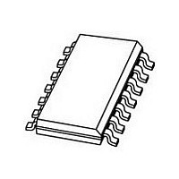
TJA1054AT NXP Semiconductors, TJA1054AT Datasheet - Page 16

TJA1054AT
Manufacturer Part Number
TJA1054AT
Description
TRANSCEIVER, CAN FAULT TOL, SO-14
Manufacturer
NXP Semiconductors
Datasheet
1.TJA1054AT518.pdf
(27 pages)
Specifications of TJA1054AT
Number Of Transceivers
1
Power Down Mode
Sleep/Standby
Operating Supply Voltage (max)
5.25V
Operating Supply Voltage (typ)
5V
Operating Supply Voltage (min)
4.75V
Package Type
SO
Supply Current
0.125/27mA
Operating Temperature (max)
150C
Operating Temperature (min)
-40C
Operating Temperature Classification
Automotive
Mounting
Surface Mount
Pin Count
14
Supply Voltage Range
4.75V To 5.25V
Operating Temperature Range
-40°C To +150°C
Digital Ic Case Style
SOIC
No. Of Pins
14
Svhc
No SVHC (18-Jun-2010)
Package / Case
SO
Base Number
1054
Supply
RoHS Compliant
Ic Function
CAN Transceiver
Rohs Compliant
Yes
Lead Free Status / RoHS Status
Compliant
Available stocks
Company
Part Number
Manufacturer
Quantity
Price
Part Number:
TJA1054AT
Manufacturer:
PHILIPS/飞利浦
Quantity:
20 000
Part Number:
TJA1054AT,518
Manufacturer:
NXP/恩智浦
Quantity:
20 000
Company:
Part Number:
TJA1054AT/VM
Manufacturer:
NXP
Quantity:
72 145
Part Number:
TJA1054AT/VM
Manufacturer:
NXP/恩智浦
Quantity:
20 000
Company:
Part Number:
TJA1054AT/VM,518
Manufacturer:
Maxim
Quantity:
39
Part Number:
TJA1054ATD-T
Manufacturer:
PHILIPS/飞利浦
Quantity:
20 000
NXP Semiconductors
Table 9.
V
ground; unless otherwise specified.
[1]
[2]
[3]
[4]
TJA1054A
Product data sheet
Symbol
t
n
n
rec
CC
det
rec
= 4.75 V to 5.25 V; V
All parameters are guaranteed over the virtual junction temperature range by design, but only 100 % tested at T
wafer level, and above this for cased products 100 % tested at T
For bare die, all parameters are only guaranteed if the back side of the die is connected to ground.
A local or remote wake-up event will be signalled at the transceiver pins RXD and ERR if V
To guarantee a successful mode transition under all conditions, the maximum specified time must be applied.
Dynamic characteristics
Parameter
failure recovery time
pulse-count failure
detection
number of
consecutive pulses
for failure recovery
BAT
Fig 4. Timing diagram for dynamic characteristics
= 5.0 V to 27 V; V
V
Δ V
V
V
V
CANH
CANL
CAN
RXD
TXD
[1][2][3]
V
diff
Conditions
normal operating mode
low power modes;
V
difference between CANH
and CANL; normal operating
mode and failures 1, 2, 5
and 6a;
pin ERR becomes LOW
on CANH and CANL
simultaneously;
failures 1, 2, 5 and 6a
…continued
= V
BAT
failures 3 and 3a
failures 4 and 7
failure 6
failures 3, 3a, 4 and 7
All information provided in this document is subject to legal disclaimers.
CANH
= 12 V
STB
− V
t
PD(L)
CANL
= V
Rev. 5 — 3 August 2010
CC
; T
vj
=
amb
−
40
= 25 °C, unless otherwise specified.
°
C to +150
Min
0.3
7
125
0.3
-
-
°
C; all voltages are defined with respect to
BAT
Fault-tolerant CAN transceiver
= 5.3 V to 27 V (see
Typ
-
-
-
-
4
4
t
PD(H)
TJA1054A
Max
1.6
38
750
1.6
-
-
amb
© NXP B.V. 2010. All rights reserved.
= 125 °C for dies on
Table
015aaa176
V
0 V
5 V
3.6 V
1.4 V
0 V
2.2 V
−3.2 V
−5 V
0.7V
0.3V
4).
CC
Unit
ms
μs
μs
ms
CC
CC
16 of 27


