1-747871-6 TE Connectivity, 1-747871-6 Datasheet

Conn D-Subminiature PL 9 POS 2.74mm Solder ST Thru-Hole 9 Terminal 1 Port

1-747871-6

Manufacturer Part Number
1-747871-6
Description
Conn D-Subminiature PL 9 POS 2.74mm Solder ST Thru-Hole 9 Terminal 1 Port
Manufacturer
TE Connectivity
Type
D-Subminiaturer
Datasheets

Specifications of 1-747871-6

Gender
PL
Pitch
2.74 mm
Termination Method
Solder
Mounting
Through Hole
Body Orientation
Straight
Body Material
Steel
Mounting Type
Through Hole
Connector Type
D Sub
Peak Reflow Compatible (260 C)
No
Leaded Process Compatible
No
Contact Plating
Gold
Rohs Compliant
No
Pcb Mounting Orientation
Vertical
Product Series
HD 20
Mating Connector Lock
With
Mating Connector Lock Type
Female Screwlocks, Fixed
Pcb Mount Retention
With
Shell Type
Front Metal Shell
Shell Size
1
Grounding Indents
With
Grounding Straps
Without
Pcb Mount Style
Through Hole
Color Code
None
Sealed
No
Profile
Standard
Post Size (mm [in])
0.66 [.026]
Mounting Hole Diameter (mm [in])
3.07 [.121]
Shell Material
Steel
Panel Mount Retention
Without
Female Screwlock Material
Zinc
Grounding Clips
Without
Termination Post Length (mm [in])
4.32 [0.170]
Solder Tail Contact Plating
Tin-Lead over Nickel
Number Of Positions
9
Pcb Mount Retention Type
Mounting Holes
Shell Plating
Tin
Contact Plating, Mating Area, Material
Gold (30), Gold Flash over Palladium Nickel
Contact Shape
Round
Contact Base Material
Brass
Connector Style
Plug
Ul Flammability Rating
UL 94V-0
Housing Material
Thermoplastic - GF
Rohs/elv Compliance
ELV compliant, 5 of 6 Compliant
Lead Free Solder Processes
Wave solder capable to 240°C, Wave solder capable to 260°C, Wave solder capable to 265°C
Pcb Thickness, Recommended (in [mm])
0.093 – 0.125 [2.36 – 3.18]
Application
Standard

Available stocks

Company
Part Number
Manufacturer
Quantity
Price
Part Number:
1-747871-6
Manufacturer:
TE Connectivity AMP Connectors
Quantity:
59 457
1.
1.1.
1.2.
2.
3.
3.1.
3.2.
3.3.
©2011 Tyco Electronics Corporation,
a TE Connectivity Ltd. Company
All Rights Reserved
TE logo is a trademark.
SCOPE
Content
This specification covers perform ance, tests and quality requirem ents for the following AMPLIMITE*
printed circuit board m ounted connectors:
!
!
!
Qualification
W hen tests are perform ed on the subject product line, procedures specified in Figure 1 shall be used.
All inspections shall be perform ed using the applicable inspection plan and product drawing.
APPLICABLE DOCUM ENTS
The following TE Connectivity (TE) docum ents form a part of this specification to the extent specified
herein. In the event of conflict between the requirem ents of this specification and the product drawing,
the product drawing shall take precedence. In the event of conflict between the requirem ents of this
specification and the referenced docum ents, this specification shall take precedence.
!
!
!
!
!
!
!
REQUIREM ENTS
Design and Construction
Connectors shall be of the design, construction and physical dim ensions specified on the applicable
product drawing.
Materials
!
!
!
Ratings
!
!
!
HD-20 right angle front m etal shell for both standard tem perature processing and surface m ount
com patible processing.
HD-20 straight posted all plastic and front m etal shell.
HD-20 right angle and straight posted full m etal shell.
109-1: General Requirem ents for Test Specifications
109 Series: Test Specifications as indicated in Figure 1
109-197: TE Test Specifications vs EIA and IEC Test Methods
114-40010: Application Specification (Right Angle Front Metal Shell)
114-40013: Application Specification (Right Angle Full Metal Shell)
114-40023: Application Specification (Straight Posted Front Metal Shell)
501-168: Qualification Test Report
Contact: Copper alloy, gold and/or tin-lead plated
Housing: Glass filled nylon or polyester, UL 94V-0 rating, 94V-2 rating for all plastic HDJ
Shell: Steel, tin or zinc plated, if applicable
Voltage:
Current: See Figure 4 for applicable current carrying capability
Tem perature: -55 to 105 C
250 volts AC rm s or DC per Underwriters Laboratories
125 volts AC rm s or DC per CSA
| Indicates change
*Trademark
Product
Specification
AMPLIMITE* HD-20 PCB Mounted Connector
For latest revision, visit our website at www.te.com/documents.
For Regional Customer Service, visit our website at www.te.com
Other products, logos, and company names might be trademarks of their respective owners.
108-40025
11Mar11 Rev C
1 of 7
LOC B

Related parts for 1-747871-6

1-747871-6 Summary of contents

Page 1

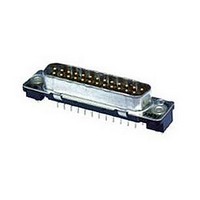
... HD-20 right angle and straight posted full m etal shell. 1.2. Qualification W hen tests are perform ed on the subject product line, procedures specified in Figure 1 shall be used. All inspections shall be perform ed using the applicable inspection plan and product drawing. 2. APPLICABLE DOCUM ENTS The following TE Connectivity (TE) docum ents form a part of this specification to the extent specified herein ...

Page 2

... Perform ance and Test Description Product is designed to m eet the electrical, m echanical and environm ental perform ance requirem ents specified in Figure 1. All tests are perform bient tem perature unless otherwise specified. 3.5. Test Requirem ents and Procedures Sum m ary Test Description Exam ination of product ...

Page 3

... TE Spec 109-42, Condition A. Measure force necessary to m ate connector assem blies using free floating fixtures at a rate of 1 inch per m inute. TE Spec 109-42, Condition A. Measure force necessary to unm ate connector assem blies at rate of 1 inch per m inute. ...

Page 4

... Tem perature rise vs current Solderability Vibration Physical shock Durability Mating force Unm ating force Therm al shock Hum idity-tem perature cycling Tem perature life Mixed flowing gas (a) See paragraph 4.1.A. NOTE (b) Numbers indicate sequence in which tests are performed. Rev C Test Group ( Test Sequence (b) ...

Page 5

... Sam ple Selection Connector housings and contacts shall be prepared in accordance with applicable Instruction Sheets and shall be selected at random from current production. Test groups and 5 shall each consist ated connector pairs with no grounding indents and shall be m ounted to a printed circuit board. Test group 5 shall be m anufactured using 30 µin gold finish. Two wires shall be used in each crim p ...

Page 6

... Mounting and Clam ping Locations for Vibration and Physical Shock Rev C Figure 3 108-40025 ...

Page 7

... Multiplication Factor (F) from the above chart and m ultiply it tim es the Base Rated Current for a single circuit at the m axim um am bient operating tem perature as shown in Figure 4A. Rev C Figure 4A Current Carrying Capability W ire Size 1.0 .71 100% .30 .20 Figure 4B Current Rating 108-40025 28 .48 . ...

Related keywords