8-1393792-5 TE Connectivity, 8-1393792-5 Datasheet - Page 377
8-1393792-5
Manufacturer Part Number
8-1393792-5
Description
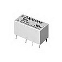
Electromechanical Relay DPDT 3A 5VDC 168Ohm Through Hole
Manufacturer
TE Connectivity
Type
Signal Relayr
Specifications of 8-1393792-5
Contact Arrangement
DPDT
Dc Coil Voltage
5 V
Coil Current
29.76 mA
Mounting
Through Hole
Relay Construction
Non-Latching
Coil Voltage Dc
5V
Contact Form
2 Form C
Voltage Rating (vdc)
220V
Voltage Rating (vac)
250V
Dropout Volt (min)
0.25VDCV
Coil Resistance
168Ohm
Pick-up Voltage (max)
4VDC
Maximum Power Rating
60W/125VA
Operate Time
5ms
Contact Current Rating
3A
Contact Material
AgNi/Au
Coil Suppression Diode
No
Push To Test Button
No
Led Indicator
No
Seal
Unsealed
Product Height (mm)
11mm
Product Depth (mm)
10mm
Product Length (mm)
20.2mm
Operating Temp Range
-25C to 85C
Pin Count
8
Mounting Style
Through Hole
Termination Style
PC Pin
Package / Case
DIP
Lead Free Status / Rohs Status
Compliant


Dimensions are shown for
reference purposes only.
Output Specification (@ 25°C, unless otherwise specified)
Electrical Characteristics (Thermal Derating Curves)
Outline Dimensions
*See Derating Curves
Operating Diagrams
• We recommend that solid state relay modules be mounted to a heatsink sufficient to maintain the module’s base temperature at less than 85°C
• The heatsink mounting surface should be a smooth (30-40 micro-inch finish), flat (30-40 micro-inch flatness across mating area), un-painted surface
• An even coating of thermal compound (Dow Corning DC340 or equivalent) should be applied to both the heatsink and module mounting surfaces
• The module should be mounted to the heatsink using two#10 screws.
Heatsink Recommendations
Parameter
Load Voltage Range V
Repetitive Blocking Voltage (Min.)
Load Current Range I *
Thermal Resistance, Junction to Case
(R
Turn-On Time (Max.)
Turn-Off Time (Max.)
I t Rating
Load Power Factor Rating
Single Cycle Surge Current (Min.)
Leakage Current (Off-State) (Max.)
On-State Voltage Drop (Max.)
Static dv/dt (Off-State) (Min.)
2
under worst case ambient temperature and load conditions.
which is clean and free of oxidation.
and spread to a uniform depth of .002” to eliminate all air pockets.
θ
j-c
CONSTANT
) (Max.)
CURRENT
DC INPUT
10A Units
+3
-4
EQUIVALENT CIRCUIT ONLY
L
L
VOLTAGE
CIRCUIT
ZERO
Dimensions are in inches over
(millimeters) unless otherwise
specified.
f = 60 Hz. V = Nom.
(120 or 240 V rms)
(22.1)
.870
(19.94)
.785
t = 8.3 ms
Conditions
f = 60 Hz.
f = 60 Hz.
I = Max.
Resistive
I = Max.
L
L
1
2
OUTPUT
Catalog 1308242
L
(6.35)
Issued 3-03
.250
Specifications and availability
subject to change.
AC INPUT
mA rms
A Sec.
25A Units
V peak
A peak
V peak
V rms
A rms
° C/W
Units
V/µs
2
ms
ms
4
3
EQUIVALENT CIRCUIT ONLY
+
& SSRT-240D10
8.3 for DC input types, 30 for AC input types
8.3 for DC input types, 20 for AC input types
SSRT-240A10
.1 - 10
1.5
100
2.2
41
VOLTAGE
CIRCUIT
ZERO
24 - 280
0.5 - 1.0
+
- 600
500
.1
& SSRT-240D25
www.tycoelectronics.com
Technical support:
Refer to inside back cover.
SSRT-240A25
.1 - 25
1.3
240
250
1.7
1
2
OUTPUT
P&B
1103
Related parts for 8-1393792-5
Image
Part Number
Description
Manufacturer
Datasheet
Request
R

Part Number:
Description:
FFC / FPC Connectors 4 13 CONDUCTOR .100 Polyester
Manufacturer:
Tyco Electronics

Part Number:
Description:
#8 PRE-INSUL SEALED SPLICE
Manufacturer:
TE Connectivity
Datasheet:

Part Number:
Description:
TERMINAL,SOLIS R 8 8
Manufacturer:
TE Connectivity
Datasheet:

Part Number:
Description:
TERMINAL, RING TONGUE 3/8IN CRIMP YELLOW
Manufacturer:
TE Connectivity
Datasheet:

Part Number:
Description:
TERMINAL, RING TONGUE, #8, CRIMP, YELLOW
Manufacturer:
TE Connectivity
Datasheet:
Part Number:
Description:
TERMINAL, RING TONGUE, 3/8IN, CRIMP
Manufacturer:
TE Connectivity
Datasheet:
Part Number:
Description:
TERMINAL, RING TONGUE, #8, CRIMP, YELLOW
Manufacturer:
TE Connectivity
Datasheet:

Part Number:
Description:
TERMINAL,R PG 8 1/4
Manufacturer:
TE Connectivity
Datasheet:

Part Number:
Description:
TERMINAL, SPADE/FORK, #8, CRIMP, YELLOW
Manufacturer:
TE Connectivity
Datasheet:
Part Number:
Description:
TERMINAL, RING TONGUE, #8, CRIMP, YELLOW
Manufacturer:
TE Connectivity
Datasheet:

Part Number:
Description:
Manufacturer:
TE Connectivity
Datasheet:


Part Number:
Description:
Manufacturer:
TE Connectivity
Datasheet:

Part Number:
Description:
SOCKET, D, R/A, 9WAY, 4-40UNC
Manufacturer:
TE Connectivity
Datasheet:
Part Number:
Description:
Electromechanical Relay SPDT 15A 12VDC 400Ohm Through Hole
Manufacturer:
TE Connectivity
Datasheet: