8-1393792-5 TE Connectivity, 8-1393792-5 Datasheet - Page 360
8-1393792-5
Manufacturer Part Number
8-1393792-5
Description
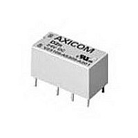
Electromechanical Relay DPDT 3A 5VDC 168Ohm Through Hole
Manufacturer
TE Connectivity
Type
Signal Relayr
Specifications of 8-1393792-5
Contact Arrangement
DPDT
Dc Coil Voltage
5 V
Coil Current
29.76 mA
Mounting
Through Hole
Relay Construction
Non-Latching
Coil Voltage Dc
5V
Contact Form
2 Form C
Voltage Rating (vdc)
220V
Voltage Rating (vac)
250V
Dropout Volt (min)
0.25VDCV
Coil Resistance
168Ohm
Pick-up Voltage (max)
4VDC
Maximum Power Rating
60W/125VA
Operate Time
5ms
Contact Current Rating
3A
Contact Material
AgNi/Au
Coil Suppression Diode
No
Push To Test Button
No
Led Indicator
No
Seal
Unsealed
Product Height (mm)
11mm
Product Depth (mm)
10mm
Product Length (mm)
20.2mm
Operating Temp Range
-25C to 85C
Pin Count
8
Mounting Style
Through Hole
Termination Style
PC Pin
Package / Case
DIP
Lead Free Status / Rohs Status
Compliant


1012
Voltage: 12VDC.
Resistance: See Coil Data table.
Nom. Power: See Coil Data table.
Thermal Resistance: 55°C per actual coil watt in still air with no contact
Features
• 20A, 16VDC switching rating.
• 75A inrush at 16VDC.
• 20A continuous contact rating @ 85°C.
• Operation to 105°C ambient.
• Immersion cleanable plastic case with knock-off nib for ventilation.
• Low profile package has a seated height of only .67” (17 mm).
• H-Bridge motor reversing arrangement.
Conditions
All parametric, environmental and life tests are performed according to EIA
Standard RS-407-A at standard test conditions (23°C Ambient, 20-50% RH,
29.5 ± 1.0” Hg.) unless otherwise noted.
Contact Data
Arrangements: 2 x 1 Form C (H-Bridge).
Material: AgNi 0.15 (consult factory for other contact materials).
Max. Switching Rate: 20 operations per second with no contact load.
Max. Switching Voltage: 24VDC.
Max. Load Current 23°C (@ 14VDC Load Voltage):
Max. Switching Power: 320 watts DC (voltage dependent)
Min. Recommended Current: 0.5 amp @ 12VDC.
Initial Voltage Drop: 400 millivolts, maximum (measured between load
Nominal Circuit Resistance: 6 milliohms load terminal to load terminal
Expected Life:
Initial Insulation Resistance @ 500VDC
Between Contacts and Coil: 10 megaohms.
Between Open Contacts: 10 megaohms.
Coil Data
Coil Data (@ 23°C Coil Temperature)
Dimensions are shown for
reference purposes only.
Continuous Carry: 20 Amperes
Intermittent Carry: 40 Amperes for 30 seconds.
Make: 75 Amperes
Break: 40 Amperes
Mechanical: 10 million operations.
Electrical: 20A, 14VDC, 1mH > 100K operations.
V2R-1001
Number
Relay
Part
40A, 14VDC, 0.5mH > 10K operations.
terminals) @ 10 amp contact load.
Rated Coil
load current.
Voltage
6 operations per minute for rated life at rated load.
(VDC)
12
@ 10 amp (this value is provided for circuit
design purposes only and is not a
specified parameter).
±10% (Ohms)
Resistance
Coil
150
Dimensions are in inches over
(millimeters) unless otherwise
specified.
Inductance
(1)
(H) (Ref.)
Coil
0.7
Catalog 1308242
Issued 3-03
Must-Operate
Voltage
(VDC)
6.0
(1) See Figure 1.
(2) See Figure 2.
(3) Current and times are compatable with circuit protection by a typical
(4) Allowable overdrive is rated at ambient temperature of 23°C and
Environmental Data
Temperature Range: Storage: -40°C to +155°C.
Shock: 20g, 11 milliseconds, half sine wave pulse.
Vibration: (For NC contacts, NO contacts are significantly higher.)
Mechanical Data
Termination: Printed circuit terminals.
Enclosure: Immersion cleanable, sealed plastic cover.
Weight: Sealed: 25 gm (0.9 oz.) approximately.
Audible Sound: 95dBA @ 10 cm, 14VDC coil voltage.
Abnormal Operation
Overload Current: 40A, 36 sec.
24V Jump Start: 24VDC for 5 minutes conducting rated contact current
Flammability: UL94V-0 (meets FMVSS 302).
Notes
V2R
20 Amp DC Motor Reversing
PC Board Relay
for Automotive Applications
Operate Data
Must Operate and Must Release Voltage: See Coil Data table.
Initial Operate Time: 5 milliseconds, typical, with rated coil voltage
Initial Release Time: 2 milliseconds, typical, with zero volts applied (for
Drop Test: Capable of meeting specifications after a 1.0 meter drop onto
Users should thoroughly review the technical data before selecting a product part
number. It is recommended that users also seek out the pertinent approvals files of
the agencies/laboratories and review them to ensure the product meets the
requirements for a given application.
Specifications and availability
subject to change.
20A circuit breaker. Relay will make, carry and break the specified
current.
105°C, as stated, with a 10A load current flowing throuth the relay
contacts and minimum coil resistance with power applied for 30 sec.
max. (20% max. duty cycle). For continuous duty information, see
Figure 2 (AmbientTemperature vs. Coil Voltage for Continuous Duty.)
10-40 Hz., 1.27mm double amplitude.
40-70 Hz., 5g's constant.
70-100 Hz., 0.5mm double amplitude.
100-500 Hz., 10g's constant.
Must-Release
concrete in final enclosure.
series
Voltage
(VDC)
0.9
77dBA @ 1 M, 14VDC coil voltage.
@ 23°C.
80A, 10 sec.
150A, 2.5 sec.
Operating: -40°C to +105°C.
unsuppressed relays after having been energized at
rated coil voltage.)
applied.
Nominal
(Watts)
Power
0.93
(3)
TYCO ELECTRONICS
@ 23°C
24V
(2)
Allowable
Overdrive
www.tycoelectronics.com
Technical support:
Refer to inside back cover.
(VDC)
(4)
@ 105°C
16V
Related parts for 8-1393792-5
Image
Part Number
Description
Manufacturer
Datasheet
Request
R

Part Number:
Description:
FFC / FPC Connectors 4 13 CONDUCTOR .100 Polyester
Manufacturer:
Tyco Electronics

Part Number:
Description:
#8 PRE-INSUL SEALED SPLICE
Manufacturer:
TE Connectivity
Datasheet:

Part Number:
Description:
TERMINAL,SOLIS R 8 8
Manufacturer:
TE Connectivity
Datasheet:

Part Number:
Description:
TERMINAL, RING TONGUE 3/8IN CRIMP YELLOW
Manufacturer:
TE Connectivity
Datasheet:

Part Number:
Description:
TERMINAL, RING TONGUE, #8, CRIMP, YELLOW
Manufacturer:
TE Connectivity
Datasheet:
Part Number:
Description:
TERMINAL, RING TONGUE, 3/8IN, CRIMP
Manufacturer:
TE Connectivity
Datasheet:
Part Number:
Description:
TERMINAL, RING TONGUE, #8, CRIMP, YELLOW
Manufacturer:
TE Connectivity
Datasheet:

Part Number:
Description:
TERMINAL,R PG 8 1/4
Manufacturer:
TE Connectivity
Datasheet:

Part Number:
Description:
TERMINAL, SPADE/FORK, #8, CRIMP, YELLOW
Manufacturer:
TE Connectivity
Datasheet:
Part Number:
Description:
TERMINAL, RING TONGUE, #8, CRIMP, YELLOW
Manufacturer:
TE Connectivity
Datasheet:

Part Number:
Description:
Manufacturer:
TE Connectivity
Datasheet:


Part Number:
Description:
Manufacturer:
TE Connectivity
Datasheet:

Part Number:
Description:
SOCKET, D, R/A, 9WAY, 4-40UNC
Manufacturer:
TE Connectivity
Datasheet:
Part Number:
Description:
Electromechanical Relay SPDT 15A 12VDC 400Ohm Through Hole
Manufacturer:
TE Connectivity
Datasheet: