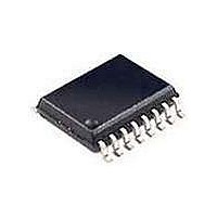
74HCT7046AD-T NXP Semiconductors, 74HCT7046AD-T Datasheet - Page 33

74HCT7046AD-T
Manufacturer Part Number
74HCT7046AD-T
Description
Phase Locked Loops (PLL) PHASED-LOCKED LOOP W/LOCK DTCT
Manufacturer
NXP Semiconductors
Type
PLLr
Datasheet
1.74HC7046AD118.pdf
(38 pages)
Specifications of 74HCT7046AD-T
Number Of Circuits
1
Supply Voltage (max)
5.5 V
Supply Voltage (min)
4.5 V
Maximum Operating Temperature
+ 125 C
Minimum Operating Temperature
- 40 C
Mounting Style
SMD/SMT
Operating Supply Voltage
5 V
Package / Case
SO-16
Lead Free Status / RoHS Status
Lead free / RoHS Compliant
Other names
74HCT7046AD,118
Philips Semiconductors
APPLICATION INFORMATION
Lock-detection circuit
The built-in lock-detection circuit will only work when used
in conjunction with the phase comparator PC2. The
lock-indication is derived from the phase error between
SIG
zero degrees over the entire VCO operating range.
However, to remain in-lock the circuit requires some small
adjustments. The variation is dependent on the loop
parameters and back-lash time (typically 5 ns). Depending
December 1990
Phase-locked-loop with lock detector
See Fig.31 for input waveform.
IN
and COMP
IN
Fig.31 Waveforms showing the lock detection process; (a) in-lock; (b) out-of-lock.
. The PC2 has a typical phase error of
Fig.30 An example of an in-lock detection circuit using the “7046A”.
(a)
33
on the application, the phase error can be defined as the
limit, a phase error of greater magnitude would be
considered out-of-lock. An example of an in-lock detection
circuit using the “7046A” is shown in Fig.30.
If the PLL is in-lock, only very small pulses will come from
the “up” or “down” connections of PC2. These pulses are
filtered out by a RC network. A Schmitt trigger produces a
steady state level, a HIGH level indicates an in-lock
condition and a pulsed output indicates an out-of-lock
condition as shown in Fig.31.
(b)
74HC/HCT7046A
Product specification


