ATF-531P8-TR1 Avago Technologies US Inc., ATF-531P8-TR1 Datasheet - Page 8
ATF-531P8-TR1
Manufacturer Part Number
ATF-531P8-TR1
Description
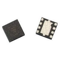
IC PHEMT 2GHZ 4V 135MA 8-LPCC
Manufacturer
Avago Technologies US Inc.
Datasheet
1.ATF-531P8-BLK.pdf
(15 pages)
Specifications of ATF-531P8-TR1
Gain
20dB
Package / Case
8-LPCC
Current Rating
300mA
Power - Output
24.5dBm
Frequency
2GHz
Transistor Type
pHEMT FET
Noise Figure
0.6dB
Current - Test
135mA
Voltage - Test
4V
Power Dissipation Pd
1W
Rf Transistor Case
LPCC
No. Of Pins
8
Frequency Max
6GHz
Noise Figure Typ
0.6dB
Frequency Min
50MHz
Continuous Drain Current Id
3.7µA
Drain Current Idss Max
135mA
Drain Source Voltage Vds
4V
Rohs Compliant
Yes
Lead Free Status / RoHS Status
Lead free / RoHS Compliant
Available stocks
Company
Part Number
Manufacturer
Quantity
Price
Company:

Part Number:
ATF-531P8-TR1
Manufacturer:
AVAGO
Quantity:
20 702
Part Number:
ATF-531P8-TR1
Manufacturer:
AVAGO/安华高
Quantity:
20 000
Company:
Part Number:
ATF-531P8-TR1G
Manufacturer:
OPTEK
Quantity:
101
Company:
Part Number:
ATF-531P8-TR1G
Manufacturer:
AVAGO
Quantity:
10 000
Part Number:
ATF-531P8-TR1G
Manufacturer:
AVAGO/安华高
Quantity:
20 000


ATF-531P8 Typical Scattering Parameters at 5°C, V
Freq.
GHz
0.1
0.2
0.3
0.4
0.5
0.6
0.7
0.8
0.9
1
1.5
1.9
2
2.4
3
4
5
6
7
8
9
10
11
12
13
14
15
16
17
18
Typical Noise Parameters at 5°C, V
Freq
GHz
0.5
0.9
1
1.5
2
2.4
3
3.5
3.9
5
5.8
6
7
8
9
10
Notes:
1. F
2. S and noise parameters are measured on a microstrip line made on 0.025 inch thick alumina carrier. The input reference plane is at the end of
8
a set of 16 noise figure measurements made at 16 different impedances using an ATN NP5 test system. From these measurements a true F
calculated.
the gate lead. The output reference plane is at the end of the drain lead.
min
values at 2 GHz and higher are based on measurements while the F
Mag.
0.626
0.704
0.761
0.794
0.815
0.824
0.834
0.840
0.845
0.848
0.854
0.857
0.853
0.853
0.855
0.858
0.864
0.871
0.869
0.880
0.883
0.884
0.874
0.874
0.877
0.884
0.894
0.896
0.898
0.918
F
dB
0.50
0.59
0.60
0.72
0.81
0.90
1.01
1.10
1.13
1.34
1.48
1.58
1.68
1.89
2.15
2.34
min
S
11
Ang.
‑59.4
‑97.4
‑119.4
‑133.8
‑142.5
‑149.6
‑155.1
‑159.7
‑163.3
‑166.4
‑177.7
175.9
174.4
168.9
161.6
150.8
140.7
131.7
123.5
115.2
106.8
95.7
85.1
74.1
63.3
57.9
46.8
43.3
31.9
20.8
Γ
Mag.
0.20
0.25
0.35
0.40
0.57
0.61
0.63
0.67
0.70
0.72
0.75
0.76
0.80
0.84
0.82
0.85
opt
Γ
Ang.
166.00
169.00
171.00
173.00
‑173.50
‑167.70
‑163.50
‑158.20
‑153.90
‑142.70
‑135.40
‑133.30
‑125.00
‑116.10
‑106.90
‑95.10
dB
33.20 45.702
31.41 37.192
29.53 29.950
27.78 24.477
26.32 20.693
24.99 17.760
23.82 15.516
22.76 13.742
21.83 12.346
20.96 11.164
17.59 7.579
15.60 6.024
15.36 5.863
13.79 4.894
11.83 3.902
9.27
7.20
5.48
4.04
2.73
1.77
0.70
‑0.34 0.962
‑1.39 0.852
‑2.52 0.748
‑3.64 0.658
‑4.81 0.575
‑5.66 0.521
‑7.25 0.434
‑8.61 0.371
opt
DS
= 4V, I
Mag.
2.906
2.292
1.879
1.593
1.370
1.226
1.084
S
DS
1
= 180 mA
R
0.041
0.044
0.036
0.039
0.029
0.033
0.041
0.054
0.068
0.139
0.229
0.278
0.470
0.860
1.170
2.010
n/50
DS
Ang.
154.5
135.8
123.5
114.8
108.9
103.9
99.9
96.6
93.6
91.0
80.6
73.9
72.6
66.5
57.9
44.6
31.6
19.4
7.5
‑4.3
‑16.1
‑29.0
‑41.6
‑52.8
‑64.5
‑74.6
‑85.4
‑93.6
‑102.6
‑110.5
= 4V, I
G
dB
28.26
24.27
24.15
21.14
20.07
18.73
16.91
15.86
15.12
13.08
12.04
11.82
10.69
9.97
8.96
8.09
a
DS
= 180 mA
mins
dB
‑40.00 0.010
‑35.92 0.016
‑34.42 0.019
‑33.56 0.021
‑32.77 0.023
‑32.77 0.023
‑32.40 0.024
‑32.40 0.024
‑32.04 0.025
‑32.04 0.025
‑31.37 0.027
‑30.75 0.029
‑30.46 0.030
‑29.90 0.032
‑29.12 0.035
‑27.74 0.041
‑26.56 0.047
‑25.35 0.054
‑24.29 0.061
‑23.35 0.068
‑22.27 0.077
‑21.41 0.085
‑20.63 0.093
‑19.91 0.101
‑19.49 0.106
‑19.02 0.112
‑18.71 0.116
‑18.49 0.119
‑18.49 0.119
‑18.94 0.113
below 2 GHz have been extrapolated. The F
Mag.
S
1
Ang.
62.6
48.8
39.1
33.7
30.0
27.4
25.8
24.6
24.2
23.8
23.5
24.4
24.9
25.8
26.6
26.5
24.3
21.2
17.4
12.6
7.0
‑0.8
‑8.8
‑16.6
‑24.6
‑31.9
‑39.8
‑47.8
‑55.1
‑62.6
Figure 28. MSG/MAG & |S21|
@ 4V, 180 mA.
-10
40
30
20
10
0
0
Mag.
0.410
0.384
0.370
0.360
0.355
0.351
0.349
0.349
0.349
0.347
0.344
0.344
0.335
0.339
0.337
0.356
0.378
0.402
0.427
0.449
0.465
0.489
0.505
0.544
0.596
0.638
0.662
0.699
0.748
0.718
MSG
S
5
S21
FREQUENCY (GHz)
Ang.
‑44.4
‑79.2
‑101.8
‑117.6
‑127.1
‑135.5
‑141.9
‑146.9
‑151.1
‑154.3
‑165.8
‑171.2
‑171.8
‑176.8
177.0
168.5
160.6
152.4
144.6
136.1
127.4
116.6
106.0
97.2
85.9
74.7
65.9
56.1
47.7
39.3
MAG
min
values are based on
10
MSG/MAG
dB
36.60
33.66
31.98
30.67
29.54
28.88
28.11
27.58
26.94
26.50
24.48
23.17
22.91
21.85
19.60
16.23
14.19
12.69
11.18
10.39
9.70
8.70
7.20
6.30
5.46
4.95
4.29
4.06
2.82
1.75
2
15
(dB)
min
20
is
Related parts for ATF-531P8-TR1
Image
Part Number
Description
Manufacturer
Datasheet
Request
R

Part Number:
Description:
IC TRANS E-PHEMT 2GHZ SOT-343
Manufacturer:
Avago Technologies US Inc.
Datasheet:

Part Number:
Description:
IC PHEMT 2GHZ 3V 30MA SOT-343
Manufacturer:
Avago Technologies US Inc.
Datasheet:

Part Number:
Description:
IC PHEMT 2GHZ 2.7V 10MA MINIPAK
Manufacturer:
Avago Technologies US Inc.
Datasheet:

Part Number:
Description:
IC PHEMT 2GHZ 2.7V 10MA SOT-343
Manufacturer:
Avago Technologies US Inc.
Datasheet:
Part Number:
Description:
IC PHEMT 2GHZ 3V 60MA SOT-343
Manufacturer:
Avago Technologies US Inc.
Datasheet:
Part Number:
Description:
IC PHEMT 1.9GHZ 80MA LN SOT-343
Manufacturer:
Avago Technologies US Inc.
Datasheet:
Part Number:
Description:
IC PHEMT 1.9GHZ 15MA LN SOT-343
Manufacturer:
Avago Technologies US Inc.
Part Number:
Description:
IC PHEMT 1.9GHZ 15MA LN SOT-343
Manufacturer:
Avago Technologies US Inc.
Datasheet:
Part Number:
Description:
IC PHEMT 1.9GHZ 60MA LN SOT-343
Manufacturer:
Avago Technologies US Inc.
Datasheet:
Part Number:
Description:
IC TRANS E-PHEMT 2GHZ SOT-343
Manufacturer:
Avago Technologies US Inc.
Datasheet:
Part Number:
Description:
IC TRANS E-PHEMT 2GHZ SOT-343
Manufacturer:
Avago Technologies US Inc.
Datasheet:
Part Number:
Description:
IC TRANS E-PHEMT 2GHZ SOT-343
Manufacturer:
Avago Technologies US Inc.
Datasheet:

Part Number:
Description:
TRANSISTOR,HEMT,N-CHAN,5.5V V(BR)DSS,175mA I(DSS),SOT-343R
Manufacturer:
Avago Technologies US Inc.
Part Number:
Description:
TRANSISTOR,HEMT,N-CHAN,3V V(BR)DSS,15mA I(DSS),SOT-363
Manufacturer:
Avago Technologies US Inc.
Datasheet:
Part Number:
Description:
TRANSISTOR,HEMT,N-CHAN,4.5V V(BR)DSS,90mA I(DSS),SOT-343R
Manufacturer:
Avago Technologies US Inc.
Datasheet: