SI7465DP-T1-E3 Vishay, SI7465DP-T1-E3 Datasheet - Page 9
SI7465DP-T1-E3
Manufacturer Part Number
SI7465DP-T1-E3
Description
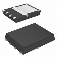
MOSFET P-CH 60V 3.2A PPAK 8SOIC
Manufacturer
Vishay
Series
TrenchFET®r
Type
Power MOSFETr
Specifications of SI7465DP-T1-E3
Transistor Polarity
P-Channel
Fet Type
MOSFET P-Channel, Metal Oxide
Fet Feature
Logic Level Gate
Rds On (max) @ Id, Vgs
64 mOhm @ 5A, 10V
Drain To Source Voltage (vdss)
60V
Current - Continuous Drain (id) @ 25° C
3.2A
Vgs(th) (max) @ Id
3V @ 250µA
Gate Charge (qg) @ Vgs
40nC @ 10V
Power - Max
1.5W
Mounting Type
Surface Mount
Package / Case
PowerPAK® SO-8
Minimum Operating Temperature
- 55 C
Configuration
Single Quad Drain Triple Source
Resistance Drain-source Rds (on)
0.064 Ohm @ 10 V
Drain-source Breakdown Voltage
60 V
Gate-source Breakdown Voltage
+/- 20 V
Continuous Drain Current
3.2 A
Power Dissipation
1500 mW
Maximum Operating Temperature
+ 150 C
Mounting Style
SMD/SMT
Continuous Drain Current Id
-5A
Drain Source Voltage Vds
-60V
On Resistance Rds(on)
80mohm
Rds(on) Test Voltage Vgs
20V
Threshold Voltage Vgs Typ
-3V
Number Of Elements
1
Polarity
P
Channel Mode
Enhancement
Drain-source On-res
0.064Ohm
Drain-source On-volt
60V
Gate-source Voltage (max)
±20V
Operating Temp Range
-55C to 150C
Operating Temperature Classification
Military
Mounting
Surface Mount
Pin Count
8
Package Type
PowerPAK SO
Lead Free Status / RoHS Status
Lead free / RoHS Compliant
Lead Free Status / RoHS Status
Lead free / RoHS Compliant, Lead free / RoHS Compliant
Other names
SI7465DP-T1-E3TR
Available stocks
Company
Part Number
Manufacturer
Quantity
Price
Company:

Part Number:
SI7465DP-T1-E3
Manufacturer:
Vishay/Siliconix
Quantity:
128 507
Company:
Part Number:
SI7465DP-T1-E3
Manufacturer:
VISHAY
Quantity:
21 676
Part Number:
SI7465DP-T1-E3
Manufacturer:
VISHAY/威世
Quantity:
20 000


THERMAL PERFORMANCE
Introduction
A basic measure of a device’s thermal performance is
the junction-to-case thermal resistance, Rθ
junction-to-foot thermal resistance, Rθ
is measured for the device mounted to an infinite heat
sink and is therefore a characterization of the device
only, in other words, independent of the properties of the
object to which the device is mounted. Table 1 shows a
comparison of the DPAK, PowerPAK SO-8, and stan-
dard SO-8. The PowerPAK has thermal performance
equivalent to the DPAK, while having an order of magni-
tude better thermal performance over the SO-8.
Thermal Performance on Standard SO-8 Pad Pattern
Because of the common footprint, a PowerPAK SO-8
can be mounted on an existing standard SO-8 pad pat-
tern. The question then arises as to the thermal perfor-
mance of the PowerPAK device under these conditions.
A characterization was made comparing a standard SO-8
and a PowerPAK device on a board with a trough cut out
underneath the PowerPAK drain pad. This configuration
restricted the heat flow to the SO-8 land pads. The
results are shown in Figure 5.
Figure 5. PowerPAK SO-8 and Standard SO-0 Land Pad Thermal Path
Document Number 71622
28-Feb-06
TABLE 1.
Resistance Rθ
Thermal
60
50
40
30
20
10
0
0.0001
Equivalent Steady State Performance
Si4874DY vs. Si7446DP PPAK on a 4-Layer Board
jc
DPAK and PowerPAK SO-8
SO-8 Pattern, Trough Under Drain
0.01
1.2 °C/W
DPAK
Pulse Duration (sec)
Si4874DY
1
PowerPAK
1.0 °C/W
SO-8
Si7446DP
100
jf
. This parameter
10000
jc
Standard
16 °C/W
, or the
SO-8
Because of the presence of the trough, this result sug-
gests a minimum performance improvement of 10 °C/W
by using a PowerPAK SO-8 in a standard SO-8 PC
board mount.
The only concern when mounting a PowerPAK on a
standard SO-8 pad pattern is that there should be no
traces running between the body of the MOSFET.
Where the standard SO-8 body is spaced away from the
pc board, allowing traces to run underneath, the Power-
PAK sits directly on the pc board.
Thermal Performance - Spreading Copper
Designers may add additional copper, spreading cop-
per, to the drain pad to aid in conducting heat from a
device. It is helpful to have some information about the
thermal performance for a given area of spreading cop-
per.
Figure 6 shows the thermal resistance of a PowerPAK
SO-8 device mounted on a 2-in. 2-in., four-layer FR-4
PC board. The two internal layers and the backside layer
are solid copper. The internal layers were chosen as
solid copper to model the large power and ground
planes common in many applications. The top layer was
cut back to a smaller area and at each step junction-to-
ambient thermal resistance measurements were taken.
The results indicate that an area above 0.3 to 0.4 square
inches of spreading copper gives no additional thermal
performance improvement. A subsequent experiment
was run where the copper on the back-side was
reduced, first to 50 % in stripes to mimic circuit traces,
and then totally removed. No significant effect was
observed.
Figure 6. Spreading Copper Junction-to-Ambient Performance
56
51
46
41
36
0.00
0.25
(0 %, 50 %, 100 % Back Copper)
0.50
R
th
0.75
vs. Spreading Copper
1.00
100 %
1.25
Vishay Siliconix
1.50
1.75
www.vishay.com
0 %
AN821
2.00
50 %
3
Related parts for SI7465DP-T1-E3
Image
Part Number
Description
Manufacturer
Datasheet
Request
R

Part Number:
Description:
P-channel 60-v D-s Mosfet
Manufacturer:
Vishay
Datasheet:

Part Number:
Description:
MOSFET P-CH 60V 3.2A PPAK 8SOIC
Manufacturer:
Vishay
Datasheet:
Part Number:
Description:
357-036-542-201 CARDEDGE 36POS DL .156 BLK LOPRO
Manufacturer:
Vishay
Datasheet:
Part Number:
Description:
357-036-542-201 CARDEDGE 36POS DL .156 BLK LOPRO
Manufacturer:
Vishay
Datasheet:
Part Number:
Description:
357-036-542-201 CARDEDGE 36POS DL .156 BLK LOPRO
Manufacturer:
Vishay
Datasheet:
Part Number:
Description:
357-036-542-201 CARDEDGE 36POS DL .156 BLK LOPRO
Manufacturer:
Vishay
Datasheet:
Part Number:
Description:
357-036-542-201 CARDEDGE 36POS DL .156 BLK LOPRO
Manufacturer:
Vishay
Datasheet:
Part Number:
Description:
357-036-542-201 CARDEDGE 36POS DL .156 BLK LOPRO
Manufacturer:
Vishay
Datasheet:
Part Number:
Description:
357-036-542-201 CARDEDGE 36POS DL .156 BLK LOPRO
Manufacturer:
Vishay
Datasheet:
Part Number:
Description:
357-036-542-201 CARDEDGE 36POS DL .156 BLK LOPRO
Manufacturer:
Vishay
Datasheet:
Part Number:
Description:
357-036-542-201 CARDEDGE 36POS DL .156 BLK LOPRO
Manufacturer:
Vishay
Datasheet:
Part Number:
Description:
357-036-542-201 CARDEDGE 36POS DL .156 BLK LOPRO
Manufacturer:
Vishay
Datasheet:
Part Number:
Description:
357-036-542-201 CARDEDGE 36POS DL .156 BLK LOPRO
Manufacturer:
Vishay
Datasheet:
Part Number:
Description:
357-036-542-201 CARDEDGE 36POS DL .156 BLK LOPRO
Manufacturer:
Vishay
Datasheet:
Part Number:
Description:
357-036-542-201 CARDEDGE 36POS DL .156 BLK LOPRO
Manufacturer:
Vishay
Datasheet: