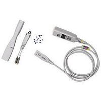
1132A AGILENT TECHNOLOGIES, 1132A Datasheet - Page 21

1132A
Manufacturer Part Number
1132A
Description
TEST PROBE, OSCILLOSCOPE
Manufacturer
AGILENT TECHNOLOGIES
Datasheet
1.E2609B.pdf
(45 pages)
Specifications of 1132A
Test Probe Type
Oscilloscope
Test Probe Functions
High Frequency
Accuracy
± 3%
For Use With
Infiniium Series Oscilliscopes
Lead Free Status / RoHS Status
na
High-Frequency Active Single-Ended Voltage Probes
Agilent 1156A/57A/58A High-Bandwidth, Active Single-Ended Voltage
Specifications
Operating Characteristics
Bandwidth (–3 dB)
System bandwidth (–3 dB)
Rise and fall time (10% to 90%)
calculated from t
Input capacitance
Input resistance [1]
Flatness, swept response
Flatness, step response
Dynamic range [2]
dc attenuation [1]
Zero offset error
referred to input [1]
Offset range [1]
Offset accuracy [1]
Noise referred to input
Propagation delay
Maximum input voltage
ESD tolerance
Temperature drift
[1] Denotes warranted specifications, all others are typical.
[2] For waveforms with edges > 3 ns, the dynamic range is > 12.0 V peak-to-peak.
[3] Installation category (over voltage category) I: Signal level, special equipment, or parts of equipment, telecommuni-
[4] Probe calibrated to scope channel (under Probes Setup menu).
Environmental Characteristics
Temperature
Humidity
cation, electronic, etc., with smaller transient overvoltage than installation category (overvoltage category) II.
r
= 0.35/bandwidth
1156A: > 1.5 GHz; 1157A: > 2.5 GHz; 1158A: > 4 GHz
1156A with MSO/DSO8104A, 54832B/D, 54833A/D
scope: 1 GHz;
1157A with 54852A scope: 2 GHz;
1157A with 54853A scope: 2.5 GHz;
1158A with 54854A scope: 4 GHz
1156A: < 233 ps; 1157A: < 140 ps; 1158A: < 88 ps
0.8 pF
100 kΩ 1%
0.2 dB: 100 kHz to 100 MHz;
0.4 dB: 100 MHz to 2.5 GHz;
2.0 dB: 2.5 GHz to 4.0 GHz
15% overshoot: 35 ps input edge;
10% overshoot: 75 ps input edge; 2%: 1 ns after edge
> 5.0 V peak-to-peak
10:1 ± 3% before calibration [4];
10:1 ± 1% after calibration [4]
< 30 mV before calibration [4];
< 5 mV after calibration [4]
±15.0 V
< 3% of setting before calibration [4];
1% of setting after calibration [4]
3.0 mVrms
5.5 ns
40 V peak, CAT I [3]
> 5 kV from 100 pF, 300 Ω HBM
Offset: < 1.0 mV/°C; Attenuation (Gain): 0.1 %/°C
Operating: 0° C to +55° C;
Non-operating: –40° C to +70° C
Operating: Up to 95% relative humidity
(non-condensing) at +40° C;
Non-operating: Up to 90% relative humidity at +65° C
Figure 3.11. Notice how closely output
matches input. Graph shows V
when driven from a 25 Ω source.
Figure 3.12. The flat response means the
waveform on the scope screen will match
the waveform at the probe tip—across
an entire 4 GHz bandwidth. Graph shows
response (V
out
/V
in
).
in
and V
out
21


