72-7222 TENMA, 72-7222 Datasheet
72-7222
Specifications of 72-7222


72-7222 Summary of contents
Page 1
... 72-7222 ...
Page 2
... D. Testing Diodes E. Testing for Continuity F. Temperature Measurement G. AC Current Measurement Sleep Mode Specifications A. General Specifications B. Environmental Restriction Accuracy Specifications A. AC Voltage B. DC Voltage C. Resistance D. Continuity Test E. Diode Test F. Temperature G. AC Current Maintenance A. General Service B. Replacing the Battery Model 72-7222: OPERATING MANUAL Page ...
Page 3
... Model 72-7222: OPERATING MANUAL 2 ...
Page 4
... To avoid electric shock or personal injury, read the “Safety Information” and “Rules for Safe Operation” carefully before using the Meter. The Digital Clamp Multimeter Model #72-7222 (hereafter referred to as “the Meter” 1/2 digits with precise operation, fashionable structure and highly reliable measuring instrument ...
Page 5
... Model 72-7222: OPERATING MANUAL Inspection Open the package case and take out the Meter. Check the following items carefully to see if any items are missing or damaged. Item Description 1 English Operating Manual 2 Test Lead Point Contact Temperature Probe 3 4 1.5V Battery (AAA) In the event you find any items missing or damaged, please contact your dealer immediately ...
Page 6
... In this manual, a Warning identifies conditions and actions that pose hazards to the user, or may damage the Meter or the equipment under test. A Note identifies the information that user should pay attention to. International electrical symbols used on the Meter and in this Operating Manual are explained on page 8. Model 72-7222: OPERATING MANUAL 5 ...
Page 7
... Model 72-7222: OPERATING MANUAL Rules For Safe Operation (1) Warning To avoid possible electric shock or personal injury, and to avoid possible damage to the Meter or to the equipment under test, adhere to the following rules: l Before using the Meter inspect the case. Do not use the Meter damaged or the case (or part of the case) is removed ...
Page 8
... Turn the Meter off when it is not in use and take out the battery when not using for a long time. l Periodically check the battery as it may leak after some time. If leakage is apparent, the battery should be immediately replaced to prevent damage to the Meter. Model 72-7222: OPERATING MANUAL 7 ...
Page 9
... Model 72-7222: OPERATING MANUAL International Electrical Symbols AC (Alternating Current). DC (Direct Current DC. Ground. Double Insulated. Low Battery Continuity Test. Diode. Capacitance Test Fuse. Warning. Refer to the Operating Manual. Conforms to Standards of European Union. 8 ...
Page 10
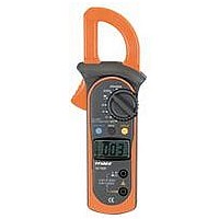
... Trigger: press the lever to open the transformer jaws. When the pressure on the lever is released, the jaws will close. 6. Hand Guards: to protect user’s hand from touching the dangerous area. 7. Transformer Jaws: designed to pick up the AC current flowing through the conductor. Model 72-7222: OPERATING MANUAL (see figure 1) 9 ...
Page 11
... Model 72-7222: OPERATING MANUAL Rotary Switch The following table provides information regarding the Rotary Switch positions. Rotary Switch Position OFF Power is turned off. AC/DC voltage measurement. : Diode test. : Continuity test. : Resistance measurement. Temperature measurement AC current measurement range from 0.001A A to 400.0A ...
Page 12
... Hold mode in any mode, the Meter beeps. l Press and hold HOLD while turning on the Meter to display full icons. MAX Press MAX to start recording and updating of maximum values. SELECT Press SELECT button to switch between and Model 72-7222: OPERATING MANUAL to enter and exit the button ...
Page 13
... Model 72-7222: OPERATING MANUAL The Effectiveness of Not every function button is used in every rotary switch position. The table below indicates which button can be used in which switch position. Rotary Switch Position K-Type) 2/20A A A 200/400A Function Button Use Function Button SELECT MAX N/A ...
Page 14
... Diode test. The continuity buzzer is on. 6 MAX Maximum reading displayed 7 Date hold is active. 8 The unit of temperature Centigrade temperature o F: Fahrenheit temperature Model 72-7222: OPERATING MANUAL (see figure 2) Meaning Ohm. The unit of resistance. 3 kilohm 1000 ohms. 6 Megaohm 1,000,000 ohms. 13 ...
Page 15
... Model 72-7222: OPERATING MANUAL Display Symbols(2) No. Symbol (see figure 2) Meaning Amperes (amps). The unit of current. Volts. The unit of voltage.mV: Millivolt. -3 1x10 or 0.001 volts Indicates negative reading The input value is too large for the selected range 14 ...
Page 16
... The measured value shows on the display. Note l In each range, the Meter has an input impedance of 10M . This loading effect can cause measurement errors in high impedance circuits. If the circuit impedance is less than or equal to 10k (0.1 or less). Model 72-7222: OPERATING MANUAL (see figure 3) red black ( figure 3) V terminal . ...
Page 17
... Model 72-7222: OPERATING MANUAL Measurement Operation(2) When DC voltage measurement has been completed, disconnect the test leads from the circuit under test, and remove them from the input terminals Voltage Measurement Warning To avoid damage to the meter, or risk of personal injury, do not attempt to measure higher than 600V AC/DC, although readings may be obtained ...
Page 18
... C.Measuring Resistance ( figure 5) Warning To avoid damage to the Meter or to the devices under test, disconnect circuit power and discharge all the high-voltage capacitors before measuring resistance. Model 72-7222: OPERATING MANUAL (see figure 5) red black 17 ...
Page 19
... Model 72-7222: OPERATING MANUAL Measurement Operation(4) The resistance ranges are: 200.0 , 2.000k , 20.00k ,200k ,2.000M To measure resistance, connect the Meter as follows: 1. Insert the red test lead into the the black test lead into the COM terminal. 2. Set the rotary switch default or press SELECT button to select measurement mode ...
Page 20
... For forward voltage drop readings on any semiconductor component, place the red test lead on the component’s anode and place the black test lead on the component’s cathode. Model 72-7222: OPERATING MANUAL red black V terminal and and press SELECT 19 ...
Page 21
... Model 72-7222: OPERATING MANUAL Measurement Operation(6) Note circuit, a good diode should still produce a forward voltage drop reading of 0.5V to 0.8; however, the reverse voltage drop reading can vary depending on the resistance of other pathways between the probe tips. l Connect the test leads to the proper terminals as said above to avoid error display ...
Page 22
... The LCD displays OL indicating the circuit being tested is open. l When continuity testing has been completed, disconnect the test leads from the circuit under test, and remove them from the input terminals. Model 72-7222: OPERATING MANUAL V terminal and and press SELECT to 120 21 ...
Page 23
... Model 72-7222: OPERATING MANUAL Measurement Operation( Temperature Measurement (see figure 8) The temperature measurement ranges are - and -40 F~1832 To measure temperature, connect the Meter as follows: 1. Insert the red temperature probe into the terminal and the black temperature probe into the COM terminal. 2. Set the rotary switch to ...
Page 24
... Set the rotary switch to 2/20A 2. Press the lever to open the transformer jaws. 3. Center the conductor within the transformer jaw. The measured value shows on the display effective value of sine wave (mean value response). Model 72-7222: OPERATING MANUAL (see figure 9) or 200/400 A 23 ...
Page 25
... Model 72-7222: OPERATING MANUAL Measurement Operation(10) Note obtain accurate reading, measure only one conductor at each time. l When current measurement has been completed, press the lever to open the transformer jaw again and remove the jaw from the conductor under test. 24 ...
Page 26
... Function Buttons valid to the Rotary Switch position will be effective. See the Function Button table on Page 12. 3) The Hold function will be cancelled if the Meter is activated by pressing the HOLD button. To disable the Sleep Mode function, press and hold HOLD button while turning on the Meter. Model 72-7222: OPERATING MANUAL 25 ...
Page 27
... Model 72-7222: OPERATING MANUAL Specifications A. General Specifications: l Maximum voltage including transient overvoltage between any terminals and ground: 500V rms. l Display: 3 1/2 digits LCD display, Maximum display 1999 l Auto Polarity Display l Overload l Low battery l Measurement Speed l Measuremnet Deviation : When the conductor being l Drop Test l Max ...
Page 28
... Frequency response: 40Hz~1kHz adjust reading in accordance with effective value B. DC Voltage: Auto ranging Range Resolution 200.0mV 0.1mV 2.000V 1mV 20.00V 10mV 200.0V 100mV 600V 1V Remarks: Input impedance: 10M Model 72-7222: OPERATING MANUAL Overload Accuracy Protection (1.2%+5) 600V rms (1.5%+5) Overload Accuracy Protection (0 ...
Page 29
... Model 72-7222: OPERATING MANUAL Accuracy Specifications(2) C. Resistance: Auto ranging Range Resolution 200.0 100m 2.000k 1 20.00k 10 200.0k 100 2.000M 1k 20.00M 10k Remarks: Input impedance: 10M D. Continuity Test Range Resolution 100m Remark: l Open circuit voltage approximate 0.45V. l The buzzer may or may not beep when the resistance ...
Page 30
... Range Resolution Accuracy (4%+30) 1A 2.000A 0.001A ( 3%+12 ) (3%+12) 20.00A 0.01A (2%+8) 200.0A (1.5%+5) 0.1A 400A 1A (1%+9) Remarks: l Displays effective value of sine wave (mean value response). Model 72-7222: OPERATING MANUAL Overload Accuracy Protection o -40~0 C: (3%+9) o 0~400 C: (1%+7) o 400~1000 C: (2%+10) 600Vp o -40~32 ...
Page 31
... Model 72-7222: OPERATING MANUAL MAINTENANCE(1) This section provides basic maintenance information including battery replacement instruction. Warning Do not attempt to repair or service your Meter unless you are qualified and have the relevant calibration, performance test, and service information. To avoid electrical shock or damage to the Meter, do not allow water inside the case ...
Page 32
... Remove the old battery from the battery compartment. 5. Replace the battery with 2pcs of new 1.5V (AAA) battery. 6. Rejoin the case bottom and the battery compartment, and reinstall the screw. ** END ** This operating manual is subject to change without notice. Model 72-7222: OPERATING MANUAL ” appears. 31 ...
Page 33
... Model 72-7222: OPERATING MANUAL Copyright 2006 Tenma Test Equipment. All rights reserved. Tenma Test Equipment 405 S. Pioneer Blvd. Springboro,Ohio 45066 www.tenma.com 32 ...