PAXCDC10 Red Lion Controls, PAXCDC10 Datasheet - Page 20
PAXCDC10
Manufacturer Part Number
PAXCDC10
Description
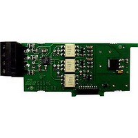
RS485 Serial Communications Output Interface Card With Terminal Block
Manufacturer
Red Lion Controls
Specifications of PAXCDC10
Accessory Type
RS485 Serial Communications Output Interface Card With Terminal Block
Brand/series
PAX Series
Card Type
RS485 Serial Communications Output Card
Data Rate
7⁄8 Bits
Standards
cULus Listed, CSA Certified and CE Marked
Voltage, Working
50 V
Pax Label Kit
189 Different Engineering Units, Labels Inserted Inside the Unit
For Use With
Red Lion PAX Digital Input Panel Meters
Lead Free Status / RoHS Status
Lead free / RoHS Compliant


the counter operating mode should be set to
indicates that Counter C is being shown in the Display Mode. An Exchange
Parameter List feature for scale factor and count load values is explained in
Module 2.
This reset action affects all Counter C resets, except the Setpoint Counter Auto
Reset Action in Module 6.
assigned to Counter C. The selection will also affect Counter C scale factor
calculations.
6.5 MODULE 5 - C
Module 5 is the programming for Counter C. For maximum input frequency,
Select the operating mode for Counter C.
When Counter C is reset, it returns to zero or Counter C count load value.
This selects the decimal point position for Counter C and any setpoint value
at the same time for the math to be performed on the display values.
the remaining related parameters are not accessible. The C annunciator
Note: When using Add Ab or Sub Ab, Counter A, B and C must all be reset
(PAXI only)
COUNTER C OPERATING MODE *
COUNTER C DECIMAL POSITION
Does not count.
Counter C counts the incoming pulses from Counter A input
as per Counter A mode of operation. The signal is scaled
only according to Counter C parameters.
Counter C counts the incoming pulses from Counter A and B
inputs as per Counter A and B modes of operation. The result
is scaled only according to Counter C parameters. (Example:
If Counter A is set for Count X1 mode and Counter B is set
for Count X2 mode, then Counter C will increment by 1 for
each pulse received on Input A and increment by 2 for each
pulse received on Input B less any effects of scaling.)
Counter C counts the incoming pulses from Counter A and B
inputs as per Counter A and B modes of operation and
subtracts the B counts from the A counts. The result is scaled
only according to Counter C parameters. (Example: If
Counter A is set for Count X1 mode and Counter B is set for
Count X2 mode, then Counter C will increment by 1 for each
pulse received on Input A and decrement by 2 for each pulse
received on Input B less any effects of scaling.)
See Serial Communications for details.
COUNTER C RESET ACTION
PAXC & I
when not in use. When set to
OUNTER
PARAMETER MENU
C I
20
NPUT
multiplier to obtain the desired process value. A scale factor of 1.00000 will
result in the display of the actual number of input counts. For
transmissions) modes of operation, the input signal is scaled directly. For
and then the result is scaled. To achieve correct results, both Input A and Input
B must provide the same amount of pulses per unit of measurement. (Details on
scaling calculations are explained at the end of Module 1 section.)
factor to obtain the desired process value. A scale multiplier of 1 will result in
only the scale factor affecting the display. (Details on scaling calculations are
explained at the end of Module 1 section.)
*
Factory Setting can be used without affecting basic start-up.
The number of input counts is multiplied by the scale factor and the scale
The number of input counts is multiplied by the scale multiplier and the scale
When reset to count load action is selected, Counter C will reset to this value.
Counter C may be programmed to reset at each meter power-up.
and
P
ARAMETERS
modes of operation, the math is performed on the input signals
COUNTER C COUNT LOAD VALUE
COUNTER C RESET POWER-UP *
COUNTER C SCALE MULTIPLIER
COUNTER C SCALE FACTOR
to
(
to
)
(Numeric
Related parts for PAXCDC10
Image
Part Number
Description
Manufacturer
Datasheet
Request
R

Part Number:
Description:
Counter
Manufacturer:
Red Lion Controls
Datasheet:
Part Number:
Description:
Miniature Length Sensor
Manufacturer:
Red Lion Controls
Datasheet:
Part Number:
Description:
Model Lsc - Single Channel Output Length Sensor
Manufacturer:
Red Lion Controls
Datasheet: