PAXCDC10 Red Lion Controls, PAXCDC10 Datasheet - Page 11
PAXCDC10
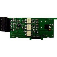
Manufacturer Part Number
PAXCDC10
Description
RS485 Serial Communications Output Interface Card With Terminal Block
Manufacturer
Red Lion Controls
Specifications of PAXCDC10
Accessory Type
RS485 Serial Communications Output Interface Card With Terminal Block
Brand/series
PAX Series
Card Type
RS485 Serial Communications Output Card
Data Rate
7⁄8 Bits
Standards
cULus Listed, CSA Certified and CE Marked
Voltage, Working
50 V
Pax Label Kit
189 Different Engineering Units, Labels Inserted Inside the Unit
For Use With
Red Lion PAX Digital Input Panel Meters
Lead Free Status / RoHS Status
Lead free / RoHS Compliant


4.5 PAXI SERIAL COMMUNICATION WIRING
RS232 Communications
50 feet. Data Terminal Equipment (DTE) transmits data on the Transmitted Data
(TXD) line and receives data on the Received Data (RXD) line. Data Computer
Equipment (DCE) receives data on the TXD line and transmits data on the RXD
line. The PAX emulates a DTE. If the other device connected to the meter also
emulates a DTE, the TXD and RXD lines must be interchanged for
communications to take place. This is known as a null modem connection. Most
printers emulate a DCE device while most computers emulate a DTE device.
without a pause in between. In these cases, the meter employs a busy function.
determine if the receiving device is “busy”. The receiving device asserts that it
is busy by setting the RXD line to a space condition (logic 0). The meter then
suspends transmission until the RXD line is released by the receiving device.
4.6 PAXI ANALOG OUTPUT WIRING
5.0 R
PAX METER (DTE)
RS232 is intended to allow two devices to communicate over distances up to
Some devices cannot accept more than two or three characters in succession
As the meter begins to transmit data, the RXD line (RS232) is monitored to
ANALOG OPTION CARD FIELD TERMINALS
16
17
18
19
** Factory setting for the F1, and F2 keys is NO mode.
*** Factory setting for the RST key is
* Counters B, and C are locked out in Factory Settings (PAXC and PAXI only).
+
-
+
-
KEY
DSP
PAR
F1
F2
RST
FEMALE
9
6
Extended Comms Connection Figure
OUTPUT
OUTPUT
0-10V
ANALOG
0-20mA
ANALOG
Terminal Block Connection Figure
5
1
EVIEWING THE
DISPLAY MODE OPERATION
Index display through the selected displays.
Access Programming Mode
Function key 1; hold for 3 seconds for Second Function 1 **
Function key 2; hold for 3 seconds for Second Function 2 **
Reset (Function key) ***
12
13
14
15
TXD
RXD
COMM.
NC
RXD
TXD
Counter
Readout
Legends*
PIN 2 TXD
PIN 3 RXD
PIN 5 COMMON
(Reset Display).
RECEIVING DEVICE
DB25
DCE
2
3
5
A
C
B
DB25
DTE
8. 8 . 8 . 8 . 8 . 8
SP1
3
2
7
DSP
F
PAR
DTE
DB9
RONT
SP2
2
3
5
F1
SP3
11
F2
4.7 PAXI PRESCALER OUTPUT WIRING
RS485 Communications
devices on a single pair of wires, distances up to 4,000 ft. and data rates as high
as 10M baud (the PAX is limited to 19.2k baud). The same pair of wires is used
to both transmit and receive data. RS485 is therefore always half-duplex, that
is, data cannot be received and transmitted simultaneously.
SP4
RST
The RS485 communication standard allows the connection of up to 32
B
PAX CONNECTOR
UTTONS AND
PROGRAMMING MODE OPERATION
Quit programming and return to Display Mode
Store selected parameter and index to next parameter
Increment selected parameter value or selections
Decrement selected parameter value or selections
Advances digit location in parameter values
Transmit
Transmit
Enable
Enable
2
3
4
Setpoint Alarm
Annunciators
Terminal Block Connection Figure
5
Extended Comms Connection Figure
PAX METER
PAX METER
+5V
+5V
33K
33K
33K
33K
12
12
13
13
14
14
15
15
B(
A(+)
NC
NC
COMM.
COMM.
(+)
-
)
*
RECEIVING DEVICE
RECEIVING DEVICE
D
* OPTIONAL
OPTIONAL
ISPLAY
Related parts for PAXCDC10
Image
Part Number
Description
Manufacturer
Datasheet
Request
R

Part Number:
Description:
Counter
Manufacturer:
Red Lion Controls
Datasheet:
Part Number:
Description:
Miniature Length Sensor
Manufacturer:
Red Lion Controls
Datasheet:
Part Number:
Description:
Model Lsc - Single Channel Output Length Sensor
Manufacturer:
Red Lion Controls
Datasheet: