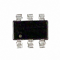
IRF5851 International Rectifier, IRF5851 Datasheet - Page 2

IRF5851
Manufacturer Part Number
IRF5851
Description
MOSFET N/PCH 20V 2.7A/2.2A 6TSOP
Manufacturer
International Rectifier
Series
HEXFET®r
Datasheet
1.IRF5851.pdf
(14 pages)
Specifications of IRF5851
Fet Type
N and P-Channel
Fet Feature
Logic Level Gate
Rds On (max) @ Id, Vgs
90 mOhm @ 2.7A, 4.5V
Drain To Source Voltage (vdss)
20V
Current - Continuous Drain (id) @ 25° C
2.7A, 2.2A
Vgs(th) (max) @ Id
1.25V @ 250µA
Gate Charge (qg) @ Vgs
6nC @ 4.5V
Input Capacitance (ciss) @ Vds
400pF @ 15V
Power - Max
960mW
Mounting Type
Surface Mount
Package / Case
Micro6™(TSOP-6)
Lead Free Status / RoHS Status
Contains lead / RoHS non-compliant
Available stocks
Company
Part Number
Manufacturer
Quantity
Price
Company:
Part Number:
IRF5851TRPBF
Manufacturer:
NIPPON
Quantity:
30 000
Part Number:
IRF5851TRPBF
Manufacturer:
IR
Quantity:
20 000
IRF5851
‚
Notes:
I
I
V
t
Q
V
∆V
R
V
g
I
Q
Q
Q
t
t
t
t
C
C
C
I
S
SM
rr
DSS
d(on)
r
d(off)
f
GSS
SD
fs
rr
(BR)DSS
GS(th)
DS(ON)
g
gs
gd
iss
oss
rss
Repetitive rating; pulse width limited by
max. junction temperature. ( See fig. 10 & 26 )
Pulse width ≤ 400µs; duty cycle ≤ 2%.
2
(BR)DSS
/∆T
J
Continuous Source Current (Body Diode)
Pulsed Source Current (Body Diode)
Diode Forward Voltage
Reverse Recovery Time
Reverse Recovery Charge
Drain-to-Source Breakdown Voltage
Breakdown Voltage Temp. Coefficient
Static Drain-to-Source On-Resistance
Gate Threshold Voltage
Forward Transconductance
Drain-to-Source Leakage Current
Gate-to-Source Forward Leakage
Total Gate Charge
Gate-to-Source Charge
Gate-to-Drain ("Miller") Charge
Turn-On Delay Time
Rise Time
Turn-Off Delay Time
Fall Time
Input Capacitance
Output Capacitance
Reverse Transfer Capacitance
Parameter
Parameter
J
N-Ch —
P-Ch —
N-Ch —
P-Ch —
N-Ch —
P-Ch —
N-Ch —
P-Ch —
N-Ch —
P-Ch —
N-Ch 20
P-Ch -20
N-Ch — 0.016 —
P-Ch — -0.011 —
N-Ch
P-Ch
N-Ch 0.60
P-Ch -0.45 —
N-Ch 5.2
P-Ch 3.5
N-Ch —
P-Ch —
N-Ch —
P-Ch —
N-Ch —
P-Ch —
N-Ch —
P-Ch —
N-Ch —
P-Ch —
N-Ch —
P-Ch —
N-Ch —
P-Ch —
N-Ch —
P-Ch —
N-Ch —
P-Ch —
N-Ch —
P-Ch —
N-Ch —
P-Ch —
N-Ch —
P-Ch —
N-P
Min. Typ. Max. Units
Min. Typ. Max. Units
—
—
—
—
––
0.95
0.66
0.83
6.5
7.7
400
320
25
23
—
— -0.96
—
—
—
—
4.0
3.6
5.7
6.6
8.3
1.2
2.4
14
15
31
28
48
56
32
40
—
—
— 0.090
— 0.120
— 0.135
— 0.220
—
—
—
—
—
—
—
— ±100
ƒ
0.96
-9.0
-1.2
1.25
1.2
9.8
-1.2
-1.0
11
38
35
12
1.0
-25
6.0
5.4
25
Surface mounted on FR-4 board, t ≤ 10sec.
—
—
—
—
—
—
—
—
—
—
—
—
—
—
—
—
—
—
—
—
—
—
Ω
T
T
N-Channel
T
P-Channel
T
N-Channel
I
P-Channel
I
N-Channel
V
P-Channel
V
N-Channel
V
P-Channel
V
V
V
Reference to 25°C, I
Reference to 25°C, I
V
V
V
V
V
V
V
V
V
V
V
V
V
V
V
D
D
J
J
J
J
DD
DD
GS
GS
GS
GS
GS
GS
DS
DS
DS
DS
DS
DS
DS
DS
GS
GS
GS
GS
GS
= 25°C, I
= 25°C, I
= -2.2A, V
= 25°C, I
= 25°C, I
= 2.7A, V
= V
= V
= -10V, I
= 16 V, V
= 16 V, V
= -16V, V
= 10V, I
= -10V, I
= 0V, I
= 0V, I
= 4.5V, I
= 2.5V, I
= -4.5V, I
= -2.5V, I
= 10V, I
= -16V, V
= ± 12V
= 0V, V
= 0V, V
= 4.5V
= -4.5V
GS
GS
, I
, I
D
D
F
F
S
S
DS
DS
DS
D
D
D
D
DS
= 250µA
= 0.96A, di/dt = 100A/µs
= -0.96A, di/dt = -100A/µs
= -250µA
D
D
D
D
= 0.96A, V
= -0.96A, V
GS
GS
D
D
= 250µA
= -250µA
GS
GS
= 1.0A, R
= 2.7A ‚
Conditions
= 10V, V
= -1.0A, R
= 2.7A ‚
= 2.2A ‚
= -2.2A ‚
= 15V, ƒ = 1.0MHz
= -15V, ƒ = 1.0MHz
= -10V, V
= -2.2A
= -1.7A
= 0V
= 0V, T
= 0V
= 0V, T
D
D
Conditions
= 1mA
= -1mA
GS
G
GS
J
J
www.irf.com
GS
GS
G
= 6.2Ω,
= 70°C
‚
‚
= 70°C
= 4.5V
= 6.0Ω
= 0V ‚
= 0V ‚
= -4.5V
‚
‚
‚


