UM5K1NTR Rohm Semiconductor, UM5K1NTR Datasheet
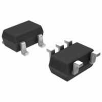
MOSFET 2N-CH 30V .1A SOT-353

UM5K1NTR

Manufacturer Part Number
UM5K1NTR
Description
MOSFET 2N-CH 30V .1A SOT-353
Manufacturer
Rohm Semiconductor
Datasheet

Specifications of UM5K1NTR

Fet Type
2 N-Channel (Dual)
Fet Feature
Logic Level Gate
Rds On (max) @ Id, Vgs
8 Ohm @ 10mA, 4V
Drain To Source Voltage (vdss)
30V
Current - Continuous Drain (id) @ 25° C
100mA
Vgs(th) (max) @ Id
1.5V @ 100µA
Input Capacitance (ciss) @ Vds
13pF @ 5V
Power - Max
150mW
Mounting Type
Surface Mount
Package / Case
SC-70-5, SC-88A, SOT-323-5, SOT-353, 5-TSSOP
Umt5
Module Configuration
Transistor Polarity
Dual N Channel
Continuous Drain Current Id
10mA
Drain Source Voltage Vds
30V
On Resistance Rds(on)
8ohm
Rds(on) Test Voltage Vgs
4V
Threshold
RoHS Compliant
Configuration
Dual Common Source
Resistance Drain-source Rds (on)
8 Ohm @ 4 V
Drain-source Breakdown Voltage
30 V
Gate-source Breakdown Voltage
+/- 20 V
Continuous Drain Current
0.1 A
Power Dissipation
150 mW
Mounting Style
SMD/SMT
Lead Free Status / RoHS Status
Lead free / RoHS Compliant
Gate Charge (qg) @ Vgs
-
Lead Free Status / Rohs Status
Lead free / RoHS Compliant

Available stocks

Company
Part Number
Manufacturer
Quantity
Price
Part Number:
UM5K1NTR
Manufacturer:
ROHM/罗姆
Quantity:
20 000
Part Number:
UM5K1NTR
0
Company:
Part Number:
UM5K1NTR
Quantity:
9 000
Transistors
2.5V Drive Nch+Nch MOS FET
UM5K1N
Silicon N-channel MOS FET
1) Two 2SK3018 transistors in a single UMT package.
2) Mounting cost and area can be cut in half.
3) Low on-resistance.
4) Low voltage drive (2.5V) makes this device ideal for
5) Drive circuits can be simple.
Interfacing, switching (30V, 100mA)
<It is the same ratings for Tr1 and Tr2.>
Channel to ambient
Type
UM5K1N
∗ With each pin mounted on the recommended lands.
Drain-source voltage
Gate-source voltage
Drain current
Total power dissipation
Channel temperature
Storage temperature
Features
Structure
Applications
Packaging specifications
Absolute maximum ratings (Ta=25°C)
Thermal resistance
portable equipment.
1 Pw≤10µs, Duty cycle≤50%
2 With each pin mounted on the recommended lands.
Package
Code
Basic ordering unit
(pieces)
Parameter
Parameter
Continuous
Pulsed
Taping
3000
TR
Symbol
V
V
Tstg
Tch
P
I
DSS
GSS
I
DP
D
D
2
1
Rth(ch-a)
Symbol
−55 to +150
Limits
±100
±400
±20
150
120
150
30
Limits
1042
833
mW / ELEMENT
mW / TOTAL
Equivalent circui
External dimensions (Unit : mm)
UMT5
Unit
mA
mA
˚C
˚C
V
V
°C / W / ELEMENT
°C / W / TOTAL
1pin mark
Unit
( 1 )
Abbreviated symbol : K1
0.65
( 5 )
( 2 ) ( 3 )
1.3
2.0
0.2
(1) Tr1 Gate
(2) Source
(3) Tr2 Gate
(4) Tr2 Drain
(6) Tr1 Drain
( 4 )
0.65
(6)
(1)
Tr1
Each lead has same dimensions
Gate
Protection
Diode
A protection diode has been built in between
the gate and the source to protect against
static electricity when the product is in use.
Use the protection circuit when rated
voltagesare exceeded.
0.15
0.9
0.7
Rev.A
(2)
UM5K1N
Gate
Protection
Diode
Tr2
(4)
(3)
1/3

Related parts for UM5K1NTR

UM5K1NTR Summary of contents

Page 1

Transistors 2.5V Drive Nch+Nch MOS FET UM5K1N Structure Silicon N-channel MOS FET Features 1) Two 2SK3018 transistors in a single UMT package. 2) Mounting cost and area can be cut in half. 3) Low on-resistance. 4) Low voltage drive (2.5V) ...

Page 2

Transistors Electrical characteristics (Ta=25°C) <It is the same characteristics for Tr1 and Tr2.> Parameter Symbol Gate-source leakage I GSS Drain-source breakdown voltage V (BR)DSS Zero gate voltage drain current I DSS Gate threshold voltage V GS(th) R DS(on) Static drain-source ...

Page 3

Transistors 9 V =4V GS Pulsed =100mA =50mA −50 − 100 125 150 CHANNEL TEMPERATURE : Tch (˚C) Fig.7 Static drain-source on-state resistance ...

Page 4

Appendix No technical content pages of this document may be reproduced in any form or transmitted by any means without prior permission of ROHM CO.,LTD. The contents described herein are subject to change without notice. The specifications for the product ...

Related keywords