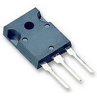
IKW40T120 Infineon Technologies, IKW40T120 Datasheet - Page 9

IKW40T120
Manufacturer Part Number
IKW40T120
Description
IGBT 1200V 75A 270W TO247-3
Manufacturer
Infineon Technologies
Series
TrenchStop™r
Datasheet
1.IKW40T120.pdf
(16 pages)
Specifications of IKW40T120
Igbt Type
NPT, Trench and Field Stop
Voltage - Collector Emitter Breakdown (max)
1200V
Vce(on) (max) @ Vge, Ic
2.3V @ 15V, 40A
Current - Collector (ic) (max)
75A
Power - Max
270W
Input Type
Standard
Mounting Type
Through Hole
Package / Case
TO-247-3 (Straight Leads)
Transistor Type
IGBT
Dc Collector Current
75A
Collector Emitter Voltage Vces
2.3V
Power Dissipation Max
270W
Collector Emitter Voltage V(br)ceo
1.2kV
Operating Temperature Range
-40°C To +150°C
Power Dissipation Pd
270W
Rohs Compliant
Yes
Switching Frequency
TRENCHSTOP 2-20kHz
Package
TO-247
Vce (max)
1,200.0 V
Ic(max) @ 25°
75.0 A
Ic(max) @ 100°
40.0 A
Lead Free Status / RoHS Status
Lead free / RoHS Compliant
Available stocks
Company
Part Number
Manufacturer
Quantity
Price
Company:
Part Number:
IKW40T120
Manufacturer:
INFINEON
Quantity:
15 000
Part Number:
IKW40T120
Manufacturer:
INFINEON/英飞凌
Quantity:
20 000
Company:
Part Number:
IKW40T120T2
Manufacturer:
INFINEON
Quantity:
12 000
Power Semiconductors
25,0mJ
20,0mJ
15,0mJ
10,0mJ
Figure 13. Typical switching energy losses
15mJ
10mJ
Figure 15. Typical switching energy losses
5,0mJ
0,0mJ
5mJ
0mJ
10A
*) E
*) E
due to diode recovery
T
as a function of collector current
(inductive load, T
V
Dynamic test circuit in Figure E)
50°C
as a function of junction
temperature
(inductive load, V
V
Dynamic test circuit in Figure E)
due to diode recovery
20A
on
J
I
CE
GE
on
,
C
and E
,
JUNCTION TEMPERATURE
=600V, V
=0/15V, I
and E
COLLECTOR CURRENT
30A
ts
ts
include losses
include losses
40A
C
GE
=40A, R
100°C
=0/15V, R
J
CE
=150°C,
50A
=600V,
G
=15Ω,
60A
G
=15Ω,
150°C
TrenchStop Series
70A
E
E
E
E
E
E
9
off
on
on
ts
ts
off
*
*
*
*
Figure 14. Typical switching energy losses
Figure 16. Typical switching energy losses
15 mJ
10 mJ
15mJ
10mJ
®
5 mJ
0 mJ
5mJ
0mJ
400V
E
E
V
E
ts
on
off
CE
*
*) E
*
*) E
as a function of gate resistor
(inductive load, T
V
Dynamic test circuit in Figure E)
as a function of collector emitter
voltage
(inductive load, T
V
Dynamic test circuit in Figure E)
,
due to diode recovery
due to diode recovery
CE
COLLECTOR
GE
on
on
500V
=600V, V
=0/15V, I
and E
R
and E
G
,
GATE RESISTOR
ts
ts
include losses
include losses
600V
-
C
GE
EMITTER VOLTAGE
=40A, R
IKW40T120
=0/15V, I
J
J
=150°C,
=150°C,
700V
Rev. 2.1
G
=15Ω,
C
=40A,
800V
May 06
E
E
E
ts
on
off
*
*


