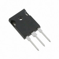
IRG7PH42UD1PBF International Rectifier, IRG7PH42UD1PBF Datasheet - Page 5

IRG7PH42UD1PBF
Manufacturer Part Number
IRG7PH42UD1PBF
Description
IGBT N-CH 1200V 85A TO-247AC
Manufacturer
International Rectifier
Datasheet
1.IRG7PH42UD1PBF.pdf
(9 pages)
Specifications of IRG7PH42UD1PBF
Igbt Type
Trench
Voltage - Collector Emitter Breakdown (max)
1200V
Vce(on) (max) @ Vge, Ic
2V @ 15V, 30A
Current - Collector (ic) (max)
85A
Power - Max
313W
Input Type
Standard
Mounting Type
Through Hole
Package / Case
TO-247-3 (Straight Leads), TO-247AC
Transistor Type
IGBT
Dc Collector Current
85A
Collector Emitter Voltage Vces
1.7V
Collector Emitter Voltage V(br)ceo
1.2kV
Operating Temperature Range
-55°C To +150°C
Transistor Case
RoHS Compliant
Package
TO-247
Circuit
Co-Pack
Switching
Soft
Switching Speed
ULTRAFAST 8-30 kHz
Vces (v)
1200
Ic @ 25c (a)
85
Ic @ 100c (a)
45
Vce(on)@25c Typ (v)
1.70
Vce(on)@25c Max (v)
2.00
Ets Typ (mj)
3.29
Ets Max (mj)
3.8
Vf Typ
1.15
Pd @25c (w)
313
Environmental Options
PbF
Lead Free Status / RoHS Status
Lead free / RoHS Compliant
www.irf.com
T
J
T
= 150°C; L = 200μH; V
J
= 150°C; L = 200μH; V
10000
1000
5000
4000
3000
2000
1000
6500
5500
4500
3500
2500
1500
100
10
0
Fig. 17 - Typ. Capacitance vs. V
Fig. 15 - Typ. Energy Loss vs. R
0
0
0
Fig. 13 - Typ. Energy Loss vs. I
10
V
25
20
GE
= 0V; f = 1MHz
20
CE
CE
50
40
= 600V, I
= 600V, R
V CE (V)
30
R G (Ω)
E OFF
I C (A)
40
75
60
E OFF
Cies
CE
Cres
Coes
G
= 10Ω; V
50
= 30A; V
100
IRG7PH42UD1PbF/IRG7PH42UD1-EP
80
C
CE
G
60
GE
125
100
GE
= 15V
70
= 15V
T
J
T
= 150°C; L = 200μH; V
J
= 150°C; L = 200μH; V
10000
1000
1000
100
100
10
Fig. 16 - Typ. Switching Time vs. R
16
14
12
10
8
6
4
2
0
Fig. 14 - Typ. Switching Time vs. I
Fig. 18 - Typical Gate Charge vs. V
0
0
0
10
20
td OFF
t F
Q G , Total Gate Charge (nC)
I
CE
50
20
V CES =600V
V CES = 400V
40
= 30A; L = 680μH
CE
CE
= 600V, R
= 600V, I
30
R G (Ω)
I C (A)
100
60
td OFF
t F
40
80
CE
G
50
= 10Ω; V
150
= 30A; V
100
C
60
G
GE
GE
120
200
GE
70
= 15V
= 15V
5


