STGF20NB60S STMicroelectronics, STGF20NB60S Datasheet - Page 3
STGF20NB60S
Manufacturer Part Number
STGF20NB60S
Description
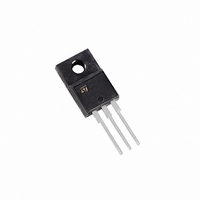
IGBT N-CH 600V 13A TO-220FP
Manufacturer
STMicroelectronics
Series
PowerMESH™r
Datasheet
1.STGF20NB60S.pdf
(11 pages)
Specifications of STGF20NB60S
Voltage - Collector Emitter Breakdown (max)
600V
Vce(on) (max) @ Vge, Ic
1.7V @ 15V, 20A
Current - Collector (ic) (max)
24A
Power - Max
40W
Input Type
Standard
Mounting Type
Through Hole
Package / Case
TO-220FP
Channel Type
N
Configuration
Single
Collector-emitter Voltage
600V
Collector Current (dc) (max)
24A
Gate To Emitter Voltage (max)
±20V
Pin Count
3 +Tab
Mounting
Through Hole
Operating Temperature (max)
150C
Operating Temperature Classification
Military
Lead Free Status / RoHS Status
Lead free / RoHS Compliant
Igbt Type
-
Lead Free Status / Rohs Status
Compliant
Available stocks
Company
Part Number
Manufacturer
Quantity
Price
Company:

Part Number:
STGF20NB60S
Manufacturer:
ST
Quantity:
12 500


ELECTRICAL CHARACTERISTICS (CONTINUED)
Table 6: Dynamic
(1) Pulsed: Pulse duration= 300 µs, duty cycle 1.5%
Table 7: Switching On
Table 8: Switching Off
Table 9: Switching Energy
(2) Eon is the turn-on losses when a typical diode is used in the test circuit in figure 2. If the IGBT is offered in a package with a co-pack
diode, the co-pack diode is used as external diode.
(3) Turn-off losses include also the tail of the collector current.
Symbol
Symbol
Symbol
Symbol
Eon (2)
Eon (2)
(di/dt)
(di/dt)
E
E
g
t
t
t
t
t
t
r
r
C
off
off
C
C
Q
d
d
fs
Q
d(on)
d(on)
(V
(V
E
E
I
Q
CL
(
(
t
t
oes
t
t
res
t
t
ies
ts
ts
ge
gc
c
off
c
off
r
r
f
f
(3)
(3)
(1)
g
off
off
on
on
)
)
)
)
Turn-on Switching Losses
Turn-off Switching Loss
Total Switching Loss
Turn-on Switching Losses
Turn-off Switching Loss
Total Switching Loss
Forward Transconductance
Input Capacitance
Output Capacitance
Reverse Transfer
Capacitance
Total Gate Charge
Gate-Emitter Charge
Gate-Collector Charge
Turn-off SOA minimum
current
Turn-on Delay Time
Current Rise Time
Turn-on Current Slope
Turn-on Delay Time
Current Rise Time
Turn-on Delay Time
Cross-over Time
Off Voltage Rise Time
Turn-off Delay Time
Current Fall Time
Cross-over Time
Off Voltage Rise Time
Turn-off Delay Time
Current Fall Time
Parameterr
Parameter
Parameter
Parameter
V
V
V
V
(see Figure 19)
V
R
V
R
(see Figure 17)
V
R
Tj= 125°C (see Figure 17)
V
R
(see Figure 18)
V
R
(see Figure 18)
V
R
T
(see Figure 17)
V
R
Tj = 125 °C
(see Figure 17)
CE
CE
CC
GE
clamp
G
CC
CC
J
CC
CC
G
G
cc
cc
G
G
G
G
= 100
= 100 , V
= 100 , V
= 25 °C
= 100 , V
= 100 , V
= 10 V
= 25 V, f= 1 MHz, V
= 100
= 100
= 480 V, I
= 15 V
= 480 V, I
= 480 V, I
= 480 V, I
= 480 V, I
= 480 V, I
= 480 V, I
= 480 V Tj = 125°C
Test Conditions
Test Conditions
Test Conditions
Test Conditions
,
I
, V
, V
C
C
C
C
GE
GE
GE
GE
C
C
C
C
= 8 A
= 20 A,
GE
GE
= 20 A,
= 20 A,
= 20 A
= 20 A
= 20 A
= 20 A
= 15V
= 15V,
= 15V,
=15V,Tj=125°C
= 15 V
= 15 V
GE
= 0
Min.
Min.
80
Min.
Min.
1820
Typ.
167
Typ.
20
27
83
10
27
340
320
Typ.
0.78
0.79
Typ.
0.84
8.24
0.86
12.4
11.5
92
70
80
73
1.6
1.1
2.4
1.1
2.4
1.2
7.4
STGF20NB60S
Max.
Max.
Max.
115
Max
Unit
A/µs
A/µs
Unit
Unit
Unit
nC
nC
nC
mJ
mJ
mJ
mJ
mJ
mJ
pF
pF
pF
µs
µs
µs
µs
µs
µs
µs
µs
ns
ns
ns
ns
S
A
3/11
Related parts for STGF20NB60S
Image
Part Number
Description
Manufacturer
Datasheet
Request
R

Part Number:
Description:
STMicroelectronics [RIPPLE-CARRY BINARY COUNTER/DIVIDERS]
Manufacturer:
STMicroelectronics
Datasheet:
Part Number:
Description:
STMicroelectronics [LIQUID-CRYSTAL DISPLAY DRIVERS]
Manufacturer:
STMicroelectronics
Datasheet:

Part Number:
Description:
BOARD EVAL FOR MEMS SENSORS
Manufacturer:
STMicroelectronics
Datasheet:
Part Number:
Description:
NPN TRANSISTOR POWER MODULE
Manufacturer:
STMicroelectronics
Datasheet:
Part Number:
Description:
TURBOSWITCH ULTRA-FAST HIGH VOLTAGE DIODE
Manufacturer:
STMicroelectronics
Datasheet:
Part Number:
Description:
Manufacturer:
STMicroelectronics
Datasheet:
Part Number:
Description:
DIODE / SCR MODULE
Manufacturer:
STMicroelectronics
Datasheet:
Part Number:
Description:
DIODE / SCR MODULE
Manufacturer:
STMicroelectronics
Datasheet:
Part Number:
Description:
Search -----> STE16N100
Manufacturer:
STMicroelectronics
Datasheet:
Part Number:
Description:
Search ---> STE53NA50
Manufacturer:
STMicroelectronics
Datasheet:
Part Number:
Description:
NPN Transistor Power Module
Manufacturer:
STMicroelectronics
Datasheet:
Part Number:
Description:
DIODE / SCR MODULE
Manufacturer:
STMicroelectronics
Datasheet: