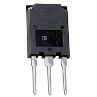
IRG4PSH71UDPBF International Rectifier, IRG4PSH71UDPBF Datasheet - Page 3

IRG4PSH71UDPBF
Manufacturer Part Number
IRG4PSH71UDPBF
Description
IGBT W/DIODE 1200V 99A SUPER247
Manufacturer
International Rectifier
Datasheet
1.IRG4PSH71UDPBF.pdf
(11 pages)
Specifications of IRG4PSH71UDPBF
Voltage - Collector Emitter Breakdown (max)
1200V
Vce(on) (max) @ Vge, Ic
2.7V @ 15V, 70A
Current - Collector (ic) (max)
99A
Power - Max
350W
Input Type
Standard
Mounting Type
Through Hole
Package / Case
Super-247-3 (Straight Leads)
Transistor Type
IGBT
Dc Collector Current
99A
Collector Emitter Voltage Vces
2.7V
Power Dissipation Pd
350W
Collector Emitter Voltage V(br)ceo
1.2kV
Operating Temperature Range
-5°C To +150°C
Rohs Compliant
Yes
Package
TO-274AA
Circuit
Co-Pack
Switching
Hard
Switching Speed
ULTRAFAST 8-30 kHz
Vces (v)
1200
Ic @ 25c (a)
99
Ic @ 100c (a)
50
Vce(on)@25c Typ (v)
2.52
Vce(on)@25c Max (v)
2.70
Ets Typ (mj)
18.2
Ets Max (mj)
19.7
Vf Typ
2.92
Pd @25c (w)
350
Environmental Options
PbF
Lead Free Status / RoHS Status
Lead free / RoHS Compliant
Igbt Type
-
Other names
*IRG4PSH71UDPBF
Available stocks
Company
Part Number
Manufacturer
Quantity
Price
Company:
Part Number:
IRG4PSH71UDPBF
Manufacturer:
IXYS
Quantity:
30 000
www.irf.com
1000
100
0.1
10
40
30
20
10
1
0
Fig. 2 - Typical Output Characteristics
0.1
0
T J = 150°C
V CE , Collector-to-Emitter Voltage (V)
Square wave:
1
60% of rated
Ideal diodes
voltage
(For square wave, I=I
T J = 25°C
2
V GE = 15V
< 60µs PULSE WIDTH
Fig. 1 - Typical Load Current vs. Frequency
3
4
1
RMS
of fundamental; for triangular wave, I=I
5
f , Frequency ( kHz )
1000.0
Fig. 3 - Typical Transfer Characteristics
100.0
10.0
1.0
0.1
4
IRG4PSH71UDPbF
T J = 150°C
V GE, Gate-to-Emitter Voltage (V)
10
Duty cycle : 50%
Tj = 125°C
Tsink = 90°C
Gate drive as specified
Turn-on losses include
effects of
reverse recovery
Power Dissipation = 58W
6
V CC = 50V
< 60µs PULSE WIDTH
T J = 25°C
PK
)
8
3
100
10


