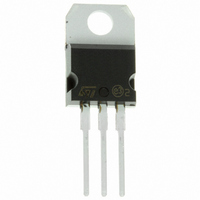
STGP7NC60H STMicroelectronics, STGP7NC60H Datasheet - Page 6

STGP7NC60H
Manufacturer Part Number
STGP7NC60H
Description
IGBT N-CHAN 25A 600V TO220
Manufacturer
STMicroelectronics
Series
PowerMESH™r
Datasheet
1.STGD7NC60HT4.pdf
(12 pages)
Specifications of STGP7NC60H
Voltage - Collector Emitter Breakdown (max)
600V
Vce(on) (max) @ Vge, Ic
2.5V @ 15V, 7A
Current - Collector (ic) (max)
25A
Power - Max
80W
Input Type
Standard
Mounting Type
Through Hole
Package / Case
TO-220-3 (Straight Leads)
Configuration
Single
Collector- Emitter Voltage Vceo Max
600 V
Maximum Gate Emitter Voltage
+/- 20 V
Maximum Operating Temperature
+ 150 C
Continuous Collector Current Ic Max
25 A
Minimum Operating Temperature
- 55 C
Mounting Style
Through Hole
Transistor Type
IGBT
Dc Collector Current
25A
Collector Emitter Voltage Vces
2.5V
Power Dissipation Pd
80W
Collector Emitter Voltage V(br)ceo
600V
Transistor Case Style
TO-247
No. Of Pins
3
Svhc
No SVHC
Rohs Compliant
Yes
Operating Temperature Range
-55°C To +150°C
Lead Free Status / RoHS Status
Lead free / RoHS Compliant
Igbt Type
-
Lead Free Status / Rohs Status
Lead free / RoHS Compliant
Other names
497-4113-5
Available stocks
Company
Part Number
Manufacturer
Quantity
Price
Company:
Part Number:
STGP7NC60H
Manufacturer:
ST
Quantity:
12 500
Company:
Part Number:
STGP7NC60HD
Manufacturer:
SANYO
Quantity:
30 000
Part Number:
STGP7NC60HD
Manufacturer:
ST
Quantity:
20 000
STGP7NC60H - STGD7NC60H
6/12
Figure 15: Thermal Impedance for TO-220
Figure 16: Thermal Impedance for DPAK
Figure 17: Turn-Off SOA
Figure 18: Ic vs Frequency
For a fast IGBT suitable for high frequency appli-
cations, the typical collector current vs. maximum
operating frequency curve is reported. That fre-
quency is defined as follows:
1) The maximum power dissipation is limited by
maximum junction to case thermal resistance:
considering T = T
2) The conduction losses are:
with 50% of duty cycle, V
@125°C.
3) Power dissipation during ON & OFF commuta-
tions is due to the switching frequency:
4) Typical values @ 125°C for switching losses are
used (test conditions: V
R
ergy is included in the E
tail of the collector current is included in the E
measurements (see note 3).
G
= 3.3 Ohm). Furthermore, diode recovery en-
f
MAX
P
SW
P
P
= (P
C
J
D
= (E
= I
- T
= T / R
D
C
C
ON
ON
- P
CE
* V
= 125 °C- 75 °C = 50°C
C
(see note 2), while the
+ E
CE(SAT)
= 390V, V
) / (E
CESAT
THJ-C
OFF
ON
) * freq.
*
typical value
+ E
GE
OFF
= 15V,
)
OFF


