STGP7NC60H STMicroelectronics, STGP7NC60H Datasheet
STGP7NC60H
Specifications of STGP7NC60H
Available stocks


Related parts for STGP7NC60H


STGP7NC60H Summary of contents
Page 1
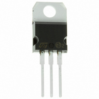
... HIGH FREQUENCY INVERTERS SMPS AND PFC IN BOTH HARD SWITCH AND RESONANT TOPOLOGIES MOTOR DRIVERS Table 2: Order Code PART NUMBER STGP7NC60H STGD7NC60HT4 June 2005 STGP7NC60H - STGD7NC60H N-CHANNEL 14A - 600V TO-220/DPAK Very Fast PowerMESH™ IGBT Figure 1: Package (Max) I CE(sat) C @25°C @100°C < ...
Page 2
... STGP7NC60H - STGD7NC60H Table 3: Absolute Maximum ratings Symbol V Collector-Emitter Voltage (V CES V Emitter-Collector Voltage ECR V Gate-Emitter Voltage GE I Collector Current (continuous Collector Current (continuous Collector Current (pulsed Total Dissipation at T TOT Derating Factor T Storage Temperature stg T Operating Junction Temperature Pulse width limited by max. junction temperature. ...
Page 3
... Eon is the turn-on losses when a typical diode is used in the test circuit in figure 2. If the IGBT is offered in a package with a co-pack diode, the co-pack diode is used as external diode. IGBTs & DIODE are at the same temperature (25°C and 125°C) (3)Turn-off losses include also the tail of the collector current. STGP7NC60H - STGD7NC60H Test Conditions V ...
Page 4
... STGP7NC60H - STGD7NC60H Figure 3: Output Characteristics Figure 4: Transconductance Figure 5: Collector-Emitter On Voltage vs Col- lector Current 4/12 Figure 6: Transfer Characteristics Figure 7: Collector-Emitter On Voltage vs Tem- perature Figure 8: Normalized Gate Threshold vs Tem- perature ...
Page 5
... Figure 9: Normalized Breakdown Voltage vs Temperature Figure 10: Capacitance Variations Figure 11: Total Switching Losses vs Gate Re- sistance STGP7NC60H - STGD7NC60H Figure 12: Gate Charge vs Gate-Emitter Volt- age Figure 13: Total Switching Losses vs Temper- ature Figure 14: Total Switching Losses vs Collector Current 5/12 ...
Page 6
... STGP7NC60H - STGD7NC60H Figure 15: Thermal Impedance for TO-220 Figure 16: Thermal Impedance for DPAK Figure 17: Turn-Off SOA 6/12 Figure 18 Frequency For a fast IGBT suitable for high frequency appli- cations, the typical collector current vs. maximum operating frequency curve is reported. That fre- quency is defined as follows: ...
Page 7
... Figure 19: Test Circuit for Inductive Load Switching Figure 20: Switching Waveforms STGP7NC60H - STGD7NC60H Figure 21: Gate Charge Test Circuit 7/12 ...
Page 8
... STGP7NC60H - STGD7NC60H DIM. MIN. A 4.40 b 0.61 b1 1.15 c 0.49 D 15. 2.40 e1 4.95 F 1.23 H1 6. 3.50 L20 L30 øP 3.75 Q 2.65 8/12 TO-220 MECHANICAL DATA mm. TYP MAX. MIN. 4.60 0.173 0.88 0.024 1.70 0.045 0.70 0.019 15.75 0.60 10.40 0.393 2.70 0.094 5 ...
Page 9
... A1 0.90 A2 0.03 B 0.64 B2 5.20 C 0.45 C2 0.48 D 6.00 E 6.40 G 4.40 H 9.35 L2 0 STGP7NC60H - STGD7NC60H inch MAX. MIN. TYP. 2.40 0.087 1.10 0.035 0.23 0.001 0.90 0.025 5.40 0.204 0.60 0.018 0.60 0.019 6.20 0.236 6.60 0.252 4.60 0.173 10.10 0.368 0.031 1 ...
Page 10
... STGP7NC60H - STGD7NC60H DPAK FOOTPRINT All dimensions are in millimeters TAPE MECHANICAL DATA mm DIM. MIN. MAX 10.4 10.6 B1 12.1 D 1.5 1.6 D1 1.5 E 1.65 1.85 F 7.4 7.6 K0 2.55 2.75 P0 3.9 4.1 P1 7.9 8.1 P2 1.9 2 15.7 16.3 10/12 TAPE AND REEL SHIPMENT inch MIN. ...
Page 11
... Table 10: Revision History Date Revision 20-Aug-2004 1 09-Jun-2005 2 Description of Changes New datasheet Modified title STGP7NC60H - STGD7NC60H 11/12 ...
Page 12
... STGP7NC60H - STGD7NC60H Information furnished is believed to be accurate and reliable. However, STMicroelectronics assumes no responsibility for the consequences of use of such information nor for any infringement of patents or other rights of third parties which may result from its use. No license is granted by implication or otherwise under any patent or patent rights of STMicroelectronics. Specifications mentioned in this publication are subject to change without notice ...