SMBYW04-200 STMicroelectronics, SMBYW04-200 Datasheet - Page 2
SMBYW04-200
Manufacturer Part Number
SMBYW04-200
Description
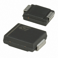
DIODE FAST REC 200V 4A SMC
Manufacturer
STMicroelectronics
Datasheet
1.SMBYW04-200.pdf
(6 pages)
Specifications of SMBYW04-200
Voltage - Forward (vf) (max) @ If
1.25V @ 12A
Voltage - Dc Reverse (vr) (max)
200V
Current - Average Rectified (io)
4A
Current - Reverse Leakage @ Vr
10µA @ 200V
Diode Type
Standard
Speed
Fast Recovery =< 500ns, > 200mA (Io)
Reverse Recovery Time (trr)
35ns
Mounting Type
Surface Mount
Package / Case
DO-214AB, SMC
Product
Fast Recovery Rectifier
Configuration
Single
Reverse Voltage
200 V
Forward Voltage Drop
1.25 V at 12 A
Recovery Time
35 ns
Forward Continuous Current
4 A
Max Surge Current
70 A
Reverse Current Ir
10 uA
Mounting Style
SMD/SMT
Maximum Operating Temperature
+ 150 C
Minimum Operating Temperature
- 65 C
Lead Free Status / RoHS Status
Contains lead / RoHS non-compliant
Capacitance @ Vr, F
-
Lead Free Status / Rohs Status
Details
Other names
497-2502-2
Available stocks
Company
Part Number
Manufacturer
Quantity
Price
Company:

Part Number:
SMBYW04-200
Manufacturer:
ST
Quantity:
20 000
Company:
Part Number:
SMBYW04-200
Manufacturer:
Mag
Quantity:
1 450


SMBYW04-200 / BYW4200B
THERMAL RESISTANCE
STATIC ELECTRICAL CHARACTERISTICS
Pulse test :
To evaluate the maximum conduction losses use the following equation :
P = 0.7 x I
RECOVERY CHARACTERISTICS
Fig. 1: Average forward power dissipation versus
average forward current.
4.5
4.0
3.5
3.0
2.5
2.0
1.5
1.0
0.5
0.0
2/6
Symbol
Symbol
Symbol
R
R
t
t
V
0.0
rr
fr
V
th (j-c)
FP
th (j-l)
I
PF(av)(W)
R
F
**
*
0.5
F(AV)
1.0
Junction to case
Junction to leads
Tj = 25°C
Tj = 25°C
Tj = 25°C
* tp = 5 ms, < 2 %
** tp = 380 s, < 2%
Reverse leakage current
Forward voltage drop
+ 0.037 I
Tests Conditions
1.5
2.0
F
2
(RMS)
2.5
IF(av) (A)
Parameter
I
V
I
V
I
F
F
F
F
FR
3.0
= 1A
= 4A
= 4A
Test Conditions
= 30V
= 1.1 x V
3.5
4.0
=tp/T
F
Tj = 25 C
Tj = 100 C
Tj = 25 C
Tj = 100 C
max
T
4.5
Tests Conditions
tp
5.0
dI
dI
dI
F
F
F
/dt = -50 A/ s
/dt = -50 A/ s
/dt = -50 A/ s
Fig. 2: Peak current versus form factor.
20
18
16
14
12
10
8
6
4
2
0
0.0
V
I
I
F
F
IM(A)
R
P=1.0W
= 12 A
= 4 A
= V
Package
0.1
DPAK
SMC
P=1.5W
RRM
0.2
Min.
0.3
P=2.0W
Min.
0.4
P=2.5W
Typ.
0.5
26
20
Typ.
0.15
5
0.8
Value
20
0.6
5
Max.
Max.
0.7
1.25
0.85
0.5
35
10
0.8
=tp/T
T
Unit
Unit
Unit
0.9
C/W
C/W
mA
ns
ns
V
V
A
tp
1.0
Related parts for SMBYW04-200
Image
Part Number
Description
Manufacturer
Datasheet
Request
R

Part Number:
Description:
STMicroelectronics [RIPPLE-CARRY BINARY COUNTER/DIVIDERS]
Manufacturer:
STMicroelectronics
Datasheet:
Part Number:
Description:
STMicroelectronics [LIQUID-CRYSTAL DISPLAY DRIVERS]
Manufacturer:
STMicroelectronics
Datasheet:

Part Number:
Description:
BOARD EVAL FOR MEMS SENSORS
Manufacturer:
STMicroelectronics
Datasheet:
Part Number:
Description:
NPN TRANSISTOR POWER MODULE
Manufacturer:
STMicroelectronics
Datasheet:
Part Number:
Description:
TURBOSWITCH ULTRA-FAST HIGH VOLTAGE DIODE
Manufacturer:
STMicroelectronics
Datasheet:
Part Number:
Description:
Manufacturer:
STMicroelectronics
Datasheet:
Part Number:
Description:
DIODE / SCR MODULE
Manufacturer:
STMicroelectronics
Datasheet:
Part Number:
Description:
DIODE / SCR MODULE
Manufacturer:
STMicroelectronics
Datasheet:
Part Number:
Description:
Search -----> STE16N100
Manufacturer:
STMicroelectronics
Datasheet:
Part Number:
Description:
Search ---> STE53NA50
Manufacturer:
STMicroelectronics
Datasheet:
Part Number:
Description:
NPN Transistor Power Module
Manufacturer:
STMicroelectronics
Datasheet:
Part Number:
Description:
DIODE / SCR MODULE
Manufacturer:
STMicroelectronics
Datasheet: