K3SC-10 AC100-240 Omron, K3SC-10 AC100-240 Datasheet - Page 5
K3SC-10 AC100-240
Manufacturer Part Number
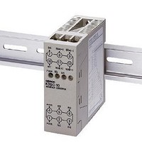
K3SC-10 AC100-240
Description
RS-232/USBto-422/485 CONVERTER
Manufacturer
Omron
Type
Interface Converterr
Datasheet
1.K3SC-10_AC100-240.pdf
(9 pages)
Specifications of K3SC-10 AC100-240
Accessory Type
Converter
Analog / Digital
Analog
Control Method
ON/OFF
Voltage Rating
100 VAC to 240 VAC
Mounting
DIN Rail
Size
30 x 80 x 78
Input Type
AC
Lead Free Status / RoHS Status
Lead free / RoHS Compliant
For Use With/related Products
RS-232C/USB and RS-422/485
Lead Free Status / Rohs Status
Lead free / RoHS Compliant
Other names
K3SC-10AC100-240
K3SC10AC100240
K3SC10AC100240


■ External Connections
RS-485 Connection
Note: 1. If RS-485 is selected as the communications method (i.e.,
Connecting an RS-232C or USB Master Device to an RS-422/485 Slave Device
First set the same communications conditions (baud rate, stop bits, data length, and parity) for the master device, the Interface Converter, and
slave devices.
Note: 1. 1-to-N connection via OMRON NT Link communications is not supported.
Connecting a USB Master Device to an RS-232C Slave Device
First set the same communications conditions (baud rate, stop bits, data length, and parity) for the master device, the Interface Converter, and
slave devices.
Note: There is no isolation between the USB and RS-232C sides.
Input power supply
(See note 2.)
Note: The USB driver is available
2. Either a 100 to 240-VAC or 24-VAC/VDC (no polarity) input
2. If the communications interface format for the master device is USB, obtain a commercially available USB cable and download the USB
pin 9 of the DIP switch is set to OFF), terminals 8 and 9, and
terminals 11 and 12 are connected internally.
power supply is used.
driver for the K3SC from the OMRON web site.
Computer
from the OMRON web site.
http://www.fa.omron.co.jp/
Computer
10
7
4
1
Note: To allow connection using a commercially available cable with an
K3SC
11
SD
8
5
2
RS-232C D-sub connector, a connection adapter (D-sub, 9-pin) is
available. (Order separately; model number: K32-23209.)
Cable with RS-232C D-sub connector
RD
12
SG
9
6
3
Note: Use a commercially available USB cable.
(See note 1.)
(See note 1.)
If the communications interface format
for the master device is RS-232C, set
pin 8 of the DIP switch to OFF.
Set pin 8 of the DIP switch to ON to select
the following communications format:
Master device: USB; Slave device: RS-232C
Slave device side
RS-485
Master device side
RS-232C
SD
RD
SG
RS
CS
DR
ER
Abbre-
viation
USB connection
(− )
(+)
Pin number (for 9-pin
computer connector)
Wire with
stranded wires.
3
2
5
7
8
6
4
K32-23209
K3SC
RS-422 Connection
Note: Either a 100 to 240-VAC or 24-VAC/VDC (no polarity) input
Wire with stranded wires.
Input power supply
(See note.)
K3SC
power supply is used.
AL 1
AL 2
HB
OT 1
OT2
Note: With RS-485 communications, connect a terminating resis-
STP
CM W
tance (120 Ω, 1/2 W recommended) to both ends of the com-
munications path.
10
SG
7
4
1
K3SC
RDA (
RDB (+) SDB (+)
RS-232C
11
SD
8
5
In addition to the required communications
conditions, set the communications number.
2
−
) SDA (
12
RD
SG
9
6
3
−
)
Devices connected
via RS-485 (example)
Measuring/testing device
Slave device side
RS-422
Master device side
RS-232C
Abbre-
viation
Abbreviation
SD
RD
SG
RS
CS
DR
ER
SDB (+)
RDB (+)
SDA (−)
RDA (−)
SG
Pin number (for 9-pin
computer connector)
3
2
5
7
8
6
4
K3SC
5
Related parts for K3SC-10 AC100-240
Image
Part Number
Description
Manufacturer
Datasheet
Request
R

Part Number:
Description:
INTERFACE CONVERTER 24VAC/VDC
Manufacturer:
Omron
Datasheet:

Part Number:
Description:
G6S-2GLow Signal Relay
Manufacturer:
Omron Corporation
Datasheet:
Part Number:
Description:
Compact, Low-cost, SSR Switching 5 to 20 A
Manufacturer:
Omron Corporation
Datasheet:
Part Number:
Description:
Manufacturer:
Omron Corporation
Datasheet:
Part Number:
Description:
Manufacturer:
Omron Corporation
Datasheet:
Part Number:
Description:
Manufacturer:
Omron Corporation
Datasheet:
Part Number:
Description:
Manufacturer:
Omron Corporation
Datasheet:
Part Number:
Description:
Manufacturer:
Omron Corporation
Datasheet:
Part Number:
Description:
Manufacturer:
Omron Corporation
Datasheet: