D4BS-K2 Omron, D4BS-K2 Datasheet - Page 8
D4BS-K2
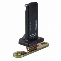
Manufacturer Part Number
D4BS-K2
Description
VERTICAL-MOUNT KEY
Manufacturer
Omron
Type
Safety-Door Switchr
Series
D4BSr
Specifications of D4BS-K2
Accessory Type
Operation Key
Contact Form
DPDT
Contact Rating
10 Amps
Actuator
Plunger
Operating Force
19.61 N
Termination Style
Wire
Svhc
No SVHC (15-Dec-2010)
Features
Vertical Mounting
Rohs Compliant
NA
Color
Black
Mounting Style
Screw
Lead Free Status / RoHS Status
Lead free / RoHS Compliant
For Use With
Z2434 - SWITCH SAFETY DOOR 10A SEALEDZ2433 - SWITCH SAFETY DOOR 10A SEAL
For Use With/related Products
D4BS Series
Lead Free Status / Rohs Status
Lead free / RoHS Compliant
Other names
D4BSK2
Z2431
Z2431


Stopper Installation
Do not use a Switch as a stoppe r. Be sure to install a stopper as
shown in the following illustration when mounting the Switch so that
the base of the Operation Key does not strike the Head.
Refer to Dimensions for the mounting dimensions of the Operation
Key and mount the Operation Key correctly. The Operation Key will
soon become damaged or worn out if it is not mounted correctly.
A-34
Cat. No. C094-E1-06
Switch
Stopper
Safety-door Switch
ALL DIMENSIONS SHOWN ARE IN MILLIMETERS.
To convert millimeters into inches, multiply by 0.03937. To convert grams into ounces, multiply by 0.03527.
Incorrect
Correct
In the interest of product improvement, specifications are subject to change without notice.
Extra space
D4BS
Set zone
Incorrect
Correct
Wiring
Do not connect the lead wires directly to the terminals. Connect the
lead wires through insulation tubes and M3.5 crimp terminals.
Tighten each terminal screw within the proper torque range.
The proper lead wire is AWG20 to AWG14 (0.5 to 2.5 mm
Wire using the methods shown below so that the crimp terminals are
not caught on the case or cover. Otherwise it may not be possible to
mount the cover completely and malfunctions may occur.
Conduit Opening
Tighten the connector to a suitable torque. Excessive tightening
torque may damage the casing.
When using 1/2-14NPT conduits, apply sealing tape between the
connector and conduit opening to maintain the degree of protection
(IP67) of the Switch. If using a Pg13.5 conduit, use an ABS-08
Pg13.5 connector or an ABS-12 Pg13.5 connector (manufactured by
Nippon Flex).
Use a connector (SC Series, sold separately) suitable for the outer
diameter of the cable.
When wiring a 3-conduit model, securely tighten the cap screw pro-
vided for unused conduit openings.
Crimp
terminal
Casing
Crimp terminal
dz dia.: 3.7
D dia.: 4.5
B:
L:
F:
I:
Correct
Incorrect
Correct
7.0
20.2
7.7
9.0 (mm)
Correct
Terminal screw
Terminal screw
Crimp terminal
D dia.
Cover
Casing
Crimp terminal
Incorrect
Incorrect
dz dia.
Terminal screw
Cover
Crimp terminal
2
) in size.
Related parts for D4BS-K2
Image
Part Number
Description
Manufacturer
Datasheet
Request
R

Part Number:
Description:
SWITCH SAFETY DOOR 10A SEALED
Manufacturer:
Omron
Datasheet:

Part Number:
Description:
Interlock Safety Door Switch
Manufacturer:
Omron
Datasheet:
Part Number:
Description:
INTERLOCK SWITCH
Manufacturer:
Omron
Datasheet:
Part Number:
Description:
SAFETY DOOR SWITCH G1/2, 2NC
Manufacturer:
Omron
Datasheet:
Part Number:
Description:
Contact OSTI For Purchase
Manufacturer:
Omron
Datasheet:
Part Number:
Description:
Limit Switch
Manufacturer:
Omron
Datasheet:
Part Number:
Description:
Safety Door Switch
Manufacturer:
Omron
Datasheet:
Part Number:
Description:
Limit Switch
Manufacturer:
Omron
Datasheet:
Part Number:
Description:
SAFETY-DOOR SWITCH
Manufacturer:
Omron
Datasheet:
Part Number:
Description:
LIMIT SWITCH ADJ ROLL LEVER
Manufacturer:
Omron
Datasheet: