D4BS-K2 Omron, D4BS-K2 Datasheet
D4BS-K2
Specifications of D4BS-K2
Z2431


Related parts for D4BS-K2


D4BS-K2 Summary of contents
Page 1
... Conduit size Pg13.5 G1/2 1/2–14NPT Pg13.5 G1/2 1/2–14NPT Operation Key D4BS - Operation Key Type 1: Horizontal mounting 2: Vertical mounting 3: Adjustable mounting (Horizontal) Note: Do not order the head and Switch separately. (The Operation Key, however, must be ordered separately.) 1NC/1NO ...
Page 2
... Operation Keys (Order Separately) Type D4BS-K1 Horizontal mounting D4BS-K2 Vertical mounting D4BS-K3 Adjustable mounting (Horizontal) Specifications ■ Standards and EC Directives • Conforms to the following EC Directives: Machinery Directive Low Voltage Directive EN50041 EN1088 ■ Approved Standard Ratings TÜV (EN60947-5-1), CCC (GB14048.5) Utilization category ...
Page 3
... Although the switch box is protected from dust, oil, or water penetration, do not use the D4BS in places where dust, oil, water, or chemicals may enter through the key hole on the head, otherwise Switch damage or malfunctioning may occur. ...
Page 4
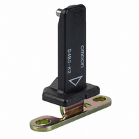
... Nomenclature Operation Key D4BS's exclusive-use Operation Key is provided to assure accurate switching operation. Set Zone Mark A triangular Set Zone Mark makes it easy to adjust the operating position when inserting the Operation Key. Built-in Switch A shearing force contact separating mechanism (NC contact) is employed, which positively pulls apart the ...
Page 5
... Six, 5.3 dia. mounting holes 30 0.2 Four, M3 cover 50.9 clamping screws Two caps Cover 17.2 51 D4BS-5@@S: Pg13.5 28.5 35.7 D4BS-6@@S: G1/2 D4BS-7@@S: 1/2-14NPT 57 38.3 63 Model D4BS-K2 20 0.15 Black 7.3 15 Two, 2.65R 5.3 5.3 7.5 2 (80.7) 36 2.5 11.4 19.5 0.15 5 (37. ...
Page 6
... D4BS-1@@S +D4BS-K1 D4BS-2@@S +D4BS-K1 D4BS-3@@S +D4BS-K1 Red 53.5 min. 58 max. Vertical Mounting D4BS-1@@S +D4BS-K2 D4BS-2@@S +D4BS-K2 54.5 min. D4BS-3@@S +D4BS-K2 59 max. Red Adjustable Mounting (Horizontal) D4BS-1@@S +D4BS-K3 D4BS-2@@S +D4BS-K3 81.5 min. D4BS-3@@S +D4BS-K3 86 max. Red Note: Unless otherwise specified, a tolerance of 0.4 mm applies to all dimensions. ...
Page 7
... Connector 1.77 to 2.16 N·m Cap screw 1.27 to 1.67 N·m Note: 1. Apply a torque of 0.78 to 0.88 N·m if the D4BS is a three- conduit model. 2. Apply a torque of 4.90 to 5.88 N·m for an Allen-head bolt. For a pan head screw, apply a torque of 2.35 to 2.75 N·m. Mounting Dimensions (M5) ...
Page 8
... ALL DIMENSIONS SHOWN ARE IN MILLIMETERS. To convert millimeters into inches, multiply by 0.03937. To convert grams into ounces, multiply by 0.03527. Cat. No. C094-E1-06 In the interest of product improvement, specifications are subject to change without notice. D4BS A-34 Safety-door Switch Wiring Do not connect the lead wires directly to the terminals. Connect the lead wires through insulation tubes and M3 ...
Page 9
... Cancellation; Etc. Orders are not subject to rescheduling or cancellation unless Buyer indemnifies Omron against all related costs or expenses. 10. Force Majeure. Omron shall not be liable for any delay or failure in delivery resulting from causes beyond its control, including earthquakes, fires, floods, strikes or other labor disputes, shortage of labor or materials, accidents to machinery, acts of sabotage, riots, delay in or lack of transportation or the requirements of any government authority ...
Page 10
Cat. No. GC SAFETY-3 07/05 Specifications subject to change without notice Printed in USA ...