D4BS-K2 Omron, D4BS-K2 Datasheet - Page 3
D4BS-K2
Manufacturer Part Number
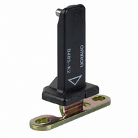
D4BS-K2
Description
VERTICAL-MOUNT KEY
Manufacturer
Omron
Type
Safety-Door Switchr
Series
D4BSr
Specifications of D4BS-K2
Accessory Type
Operation Key
Contact Form
DPDT
Contact Rating
10 Amps
Actuator
Plunger
Operating Force
19.61 N
Termination Style
Wire
Svhc
No SVHC (15-Dec-2010)
Features
Vertical Mounting
Rohs Compliant
NA
Color
Black
Mounting Style
Screw
Lead Free Status / RoHS Status
Lead free / RoHS Compliant
For Use With
Z2434 - SWITCH SAFETY DOOR 10A SEALEDZ2433 - SWITCH SAFETY DOOR 10A SEAL
For Use With/related Products
D4BS Series
Lead Free Status / Rohs Status
Lead free / RoHS Compliant
Other names
D4BSK2
Z2431
Z2431


■ Characteristics
Note: 1. The above values are initial values.
Connections
■ Contact Form (Diagrams Show State with Key Inserted)
Note: The terminal numbers are in accordance with EN50013, and the contact symbols are in accordance with IEC60947-5-1.
Degree of protection (see note 2)
Durability (see note 3)
Operating speed
Operating frequency
Rated frequency
Contact gap
Direct opening force (see note 4)
Direct opening travel (see note 4)
Full stroke
Insulation resistance
Contact resistance
Rated insulation voltage (U
Conventional enclosed thermal current
(I
Dielectric strength (U
Switching overvoltage
Conditional short-circuit current
Pollution degree
(operating environment)
Insulation class
Vibration resistance
Shock resistance
Ambient temperature
Ambient humidity
Weight
D4BS-@5@S
D4BS-@A@S
the
)
2. The degree of protection is tested using the method specified by the standard (EN60947-5-1). Confirm that sealing properties are
3. The durability is for an ambient temperature of 5 C to 35 C and an ambient humidity of 40% to 70%. Contact your OMRON sales
4. These figures are minimum requirements for safe operation.
Model
sufficient for the operating conditions and environment beforehand. Although the switch box is protected from dust, oil, or water
penetration, do not use the D4BS in places where dust, oil, water, or chemicals may enter through the key hole on the head, otherwise
Switch damage or malfunctioning may occur.
representative for more detailed information on other operating environments.
1NC/1NO
2NC
imp
)
i
)
Contact form
11
21
Zb
Zb
IP67 (EN60947-5-1) (This applies for the Switch only. The degree of protection for the key hole is
IP00.)
Mechanical: 1,000,000 operations min.
Electrical:
0.1 m/s to 0.5 m/s
30 operations/min max.
50/60 Hz
2 x 2 mm min.
19.61 N min. (EN60947-5-1)
20 mm min. (EN60947-5-1)
23 mm min.
100 M min. (at 500 VDC) between terminals of same or different polarity, between each terminal and
ground, and between each terminal and non-current-carrying metal part
25 m
600 V (EN60947-5-1)
20 A (EN60947-5-1)
Impulse dielectric strength (U
between current-carrying metal parts and ground, and between each terminal and non-current-
carrying metal part
1,500 V max. (EN60947-5-1)
100 A (EN60947-5-1)
3 (EN60947-5-1)
Class I (with ground terminal)
Malfunction: 10 to 500 Hz, 0.65-mm single amplitude
Destruction: 1,000 m/s
Malfunction: 300 m/s
Operating:
Operating:
Approx. 285 g (in the case of D4BS-15FS)
max. (initial value)
12
22
12
24
500,000 operations min. (10 A at 250 VAC, resistive load)
95% max.
40 C to 80 C (with no icing)
2
min. (IEC68-2-27)
2
11 - 12
23 - 24
11 - 12
21 - 22
min. (IEC68-2-27)
Operation Key
insertion com-
pletion position
Operation Key
insertion com-
pletion position
imp
) 4 kV (EN60947-5-1) between terminals of same or different polarity,
Operating pattern
Stroke
Stroke
Extraction
completion
position
Extraction
completion
position
Safety-door Switch
ON
ON
Only NC contact 11-12
has an approved direct
opening mechanism.
Terminals 11-12 and
23-24 can be used as
unlike poles.
NC contacts 11-12 and
21-22 have an
approved direct
opening mechanism.
Terminals 11-12 and
21-22 can be used as
unlike poles.
D4BS
Remarks
A-29
Related parts for D4BS-K2
Image
Part Number
Description
Manufacturer
Datasheet
Request
R

Part Number:
Description:
SWITCH SAFETY DOOR 10A SEALED
Manufacturer:
Omron
Datasheet:

Part Number:
Description:
Interlock Safety Door Switch
Manufacturer:
Omron
Datasheet:
Part Number:
Description:
INTERLOCK SWITCH
Manufacturer:
Omron
Datasheet:
Part Number:
Description:
SAFETY DOOR SWITCH G1/2, 2NC
Manufacturer:
Omron
Datasheet:
Part Number:
Description:
Contact OSTI For Purchase
Manufacturer:
Omron
Datasheet:
Part Number:
Description:
Limit Switch
Manufacturer:
Omron
Datasheet:
Part Number:
Description:
Safety Door Switch
Manufacturer:
Omron
Datasheet:
Part Number:
Description:
Limit Switch
Manufacturer:
Omron
Datasheet:
Part Number:
Description:
SAFETY-DOOR SWITCH
Manufacturer:
Omron
Datasheet:
Part Number:
Description:
LIMIT SWITCH ADJ ROLL LEVER
Manufacturer:
Omron
Datasheet: