STTH102 STMicroelectronics, STTH102 Datasheet
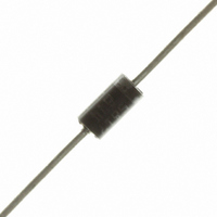
IC DIODE ULTRAFAST 220V 1A DO-41

STTH102

Manufacturer Part Number
STTH102
Description
IC DIODE ULTRAFAST 220V 1A DO-41
Manufacturer
STMicroelectronics
Datasheet

Specifications of STTH102

Voltage - Forward (vf) (max) @ If
970mV @ 1A
Voltage - Dc Reverse (vr) (max)
220V
Current - Average Rectified (io)
1A
Current - Reverse Leakage @ Vr
1µA @ 220V
Diode Type
Standard
Speed
Fast Recovery =< 500ns, > 200mA (Io)
Reverse Recovery Time (trr)
20ns
Mounting Type
Through Hole
Package / Case
DO-204AL, DO-41, Axial
Product
Ultra Fast Recovery Rectifier
Configuration
Single
Reverse Voltage
200 V
Forward Voltage Drop
0.97 V
Recovery Time
20 ns
Forward Continuous Current
1 A
Max Surge Current
50 A
Reverse Current Ir
1 uA
Mounting Style
Through Hole
Maximum Operating Temperature
+ 175 C
Minimum Operating Temperature
- 65 C
Lead Free Status / RoHS Status
Lead free / RoHS Compliant
Capacitance @ Vr, F
-
Lead Free Status / Rohs Status
Lead free / RoHS Compliant
Other names
497-3666-2
497-3666-2
497-3666-3

Available stocks

Company
Part Number
Manufacturer
Quantity
Price
Part Number:
STTH102
Manufacturer:
ST
Quantity:
20 000
Part Number:
STTH102
Manufacturer:
ST
0
Part Number:
STTH102
Manufacturer:
ST
Quantity:
180
Company:
Part Number:
STTH102
Quantity:
2 400
Part Number:
STTH102-Y
Manufacturer:
ST
0
Part Number:
STTH102A
Manufacturer:
AVAGO
Quantity:
340
Part Number:
STTH102A
Manufacturer:
STMicroelectronics
Quantity:
60 000
Part Number:
STTH102A
Manufacturer:
ST
0
Part Number:
STTH102A
Manufacturer:
ST
Quantity:
20 000
Part Number:
STTH102A-BOS
Manufacturer:
ST
0
Part Number:
STTH102A-TR
Manufacturer:
ST
0
Part Number:
STTH102RL
Manufacturer:
STMicroelectronics
Quantity:
7 996
Part Number:
STTH102RL
Manufacturer:
ST
Quantity:
5 000
Part Number:
STTH102RL
Manufacturer:
ST
Quantity:
310
Part Number:
STTH102RL
0
Main product characteristics
Features and benefits
Description
The STTH102, which is using ST’s new 200 V
planar technology, is specially suited for switching
mode base drive and transistor circuits. The
device is also intended for use as a free wheeling
diode in power supplies and other power
switching applications.
Table 1.
November 2006
Symbol
V
I
dV/dt
Very low conduction losses
Negligible switching losses
Low forward and reverse recovery times
High junction temperature
I
F(AV)
T
FSM
RRM
T
stg
j
V
t
T
rr
V
F
I
j
F(AV)
(max)
(max)
(max)
Critical rate of rise of reverse voltage
Repetitive peak reverse voltage
Average forward current
Surge non repetitive forward
current
Storage temperature range
Maximum operating junction temperature
RRM
Absolute ratings (limiting values)
175° C
0.78 V
200 V
20 ns
1 A
Parameter
SMA
DO-41
SMA
DO-41
Rev 5
T
T
tp = 10 ms Sinusoidal
L
L
Order codes
= 148° C δ = 0.5
= 130° C δ = 0.5
(JEDEC DO-214AC)
High efficiency ultrafast diode
K
Part Number
STTH102A
STTH102RL
STTH102A
STTH102
SMA
A
-65 to + 175
STTH102
10000
Value
STTH102
K
200
175
40
50
STTH102
STTH102
1
DO-41
Marking
U12
A
www.st.com
Unit
V/µs
°C
°C
V
A
A
1/7
7

Related parts for STTH102

STTH102 Summary of contents

Page 1

... Low forward and reverse recovery times ■ High junction temperature Description The STTH102, which is using ST’s new 200 V planar technology, is specially suited for switching mode base drive and transistor circuits. The device is also intended for use as a free wheeling diode in power supplies and other power switching applications ...

Page 2

... Min Typ Max 12 50 max F 1.8 Average forward power dissipation versus average forward current (DO-41) δ = 0.2 δ = 0.1 δ = 0.5 δ = 0.05 I (A) F(AV) δ =tp/T 0.25 0.50 0.75 1.00 STTH102 Unit °C/W Unit µA V Unit δ 1.25 ...

Page 3

... STTH102 Figure 3. Average forward current versus ambient temperature (δ = 0.5) (SMA) I (A) F(AV) 1.2 1.0 0.8 R =120°C/W 0.6 th(j-a) 0.4 T 0.2 T (°C) amb δ tp =tp/T 0 100 Figure 5. Relative variation of thermal impedance junction to ambient versus pulse duration (epoxy printed circuit board, e ...

Page 4

... =125° =25° /dt(A/µ 100 parameters versus junction temperature =25° F(AV) dI /dt=200A/µ =100V R T (° 100 125 lead length (DO-41) R th(j-a) R th(j-I) L (mm) leads STTH102 /dt F 1000 150 175 25 ...

Page 5

... STTH102 2 Package information ● Epoxy meets UL94 V0 Table 5. SMA Dimensions Figure 15. Footprint (dimensions in mm) Table 6. DO-41 (Plastic) Package dimensions C In order to meet environmental requirements, ST offers these devices in ECOPACK® packages. These packages have a lead-free second level interconnect. The category of second level interconnect is marked on the package and on the inner box label, in compliance with JEDEC Standard JESD97 ...

Page 6

... Jul-2003 Aug-2004 27-Jun-2005 21-Nov-2006 6/7 Marking Package U12 SMA STTH102 DO-41 STTH102 DO-41 Revision 2A Last update. SMA package dimensions update. Reference A1 max. changed 3 from 2.70mm (0.106inc.) to 2.03mm (0.080). SMA and DO-41 datasheets merged 4 Corrected error in title. Reformatted to current standards. Added Table 4. Dynamic 5 electrical characteristics ...

Page 7

... STTH102 Information in this document is provided solely in connection with ST products. STMicroelectronics NV and its subsidiaries (“ST”) reserve the right to make changes, corrections, modifications or improvements, to this document, and the products and services described herein at any time, without notice. All ST products are sold pursuant to ST’s terms and conditions of sale. ...

Related keywords