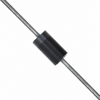
1N5821G ON Semiconductor, 1N5821G Datasheet - Page 7

1N5821G
Manufacturer Part Number
1N5821G
Description
DIODE SCHOTTKY 3A 30V DO-201AD
Manufacturer
ON Semiconductor
Specifications of 1N5821G
Voltage - Forward (vf) (max) @ If
500mV @ 3A
Voltage - Dc Reverse (vr) (max)
30V
Current - Average Rectified (io)
3A
Current - Reverse Leakage @ Vr
2mA @ 30V
Diode Type
Schottky
Speed
Fast Recovery =< 500ns, > 200mA (Io)
Mounting Type
Through Hole
Package / Case
DO-201AD, Axial
Product
Schottky Diodes
Peak Reverse Voltage
30 V
Forward Continuous Current
3 A
Max Surge Current
80 A
Configuration
Single
Forward Voltage Drop
0.9 V @ 9.4 A
Maximum Reverse Leakage Current
2000 uA
Operating Temperature Range
- 65 C to + 125 C
Mounting Style
Through Hole
Current, Forward
3 A
Current, Reverse
20 mA
Current, Surge
80 A
Package Type
DO-201AD
Primary Type
Schottky Barrier
Temperature, Junction, Maximum
+125 °C
Temperature, Operating
-65 to +125 °C
Voltage, Forward
0.5 V
Voltage, Reverse
30 V
Lead Free Status / RoHS Status
Lead free / RoHS Compliant
Reverse Recovery Time (trr)
-
Capacitance @ Vr, F
-
Lead Free Status / Rohs Status
Lead free / RoHS Compliant
Other names
1N5821G
1N5821GOS
1N5821GOS
0.07
0.05
500
300
200
100
7.0
5.0
3.0
2.0
1.0
0.7
0.5
0.3
0.2
0.1
70
50
30
20
10
0
0.5
0.1
T
f = 1.0 MHz
J
0.7
v
= 25°C
0.2
F
, INSTANTANEOUS FORWARD VOLTAGE (VOLTS)
Figure 7. Typical Forward Voltage
1.0
Figure 10. Typical Capacitance
0.3
T
V
0.4
J
R
= 100°C
, REVERSE VOLTAGE (VOLTS)
2.0
0.5
0.6
3.0
0.7
5.0
0.8
25°C
7.0
0.9
1.0
10
1N5820
1N5820, 1N5821, 1N5822
1.1
1.2
20
1N5822
http://onsemi.com
1N5821
1.3
30
1.4
7
majority carrier conduction, it is not subject to junction di‐
ode forward and reverse recovery transients due to minority
carrier injection and stored charge. Satisfactory circuit ana‐
lysis work may be performed by using a model consisting
of an ideal diode in parallel with a variable capacitance.
(See Figure 10.)
0.05
0.02
0.01
100
100
5.0
2.0
1.0
0.5
0.2
0.1
Since current flow in a Schottky rectifier is the result of
70
50
30
20
10
50
20
10
1.0
0
100°C
NOTE 6 — HIGH FREQUENCY OPERATION
T
f = 60 Hz
25°C
75°C
L
T
Figure 8. Maximum Non-Repetitive Surge
J
4.0
= 75°C
= 125°C
2.0
SURGE APPLIED AT RATED LOAD CONDITIONS
Figure 9. Typical Reverse Current
8.0
3.0
V
R
12
, REVERSE VOLTAGE (VOLTS)
5.0
NUMBER OF CYCLES
16
7.0 10
1 CYCLE
Current
20
24
20
28
30
32
1N5820
1N5821
1N5822
50 70
36
100
40


