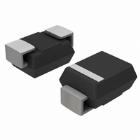
SS24T3G ON Semiconductor, SS24T3G Datasheet - Page 2

SS24T3G
Manufacturer Part Number
SS24T3G
Description
DIODE SCHOTTKY POWER 2A 40V SMB
Manufacturer
ON Semiconductor
Datasheet
1.SS24T3G.pdf
(5 pages)
Specifications of SS24T3G
Voltage - Forward (vf) (max) @ If
500mV @ 2A
Voltage - Dc Reverse (vr) (max)
40V
Current - Average Rectified (io)
2A
Current - Reverse Leakage @ Vr
400µA @ 40V
Diode Type
Schottky
Speed
Fast Recovery =< 500ns, > 200mA (Io)
Mounting Type
Surface Mount
Package / Case
DO-214AA, SMB
Product
Schottky Diodes
Peak Reverse Voltage
40 V
Forward Continuous Current
2 A
Max Surge Current
75 A
Configuration
Single
Forward Voltage Drop
0.5 V
Maximum Reverse Leakage Current
400 uA
Operating Temperature Range
- 55 C to + 125 C
Mounting Style
SMD/SMT
Lead Free Status / RoHS Status
Lead free / RoHS Compliant
Reverse Recovery Time (trr)
-
Capacitance @ Vr, F
-
Lead Free Status / Rohs Status
Lead free / RoHS Compliant
Other names
SS24T3GOS
SS24T3GOS
SS24T3GOSTR
SS24T3GOS
SS24T3GOSTR
Available stocks
Company
Part Number
Manufacturer
Quantity
Price
Company:
Part Number:
SS24T3G
Manufacturer:
ON Semiconductor
Quantity:
17 200
Part Number:
SS24T3G
Manufacturer:
ON/安森美
Quantity:
20 000
Stresses exceeding Maximum Ratings may damage the device. Maximum Ratings are stress ratings only. Functional operation above the
Recommended Operating Conditions is not implied. Extended exposure to stresses above the Recommended Operating Conditions may affect
device reliability.
1. The heat generated must be less than the thermal conductivity from Junction−to−Ambient: dP
2. Mounted with minimum recommended pad size, PC Board FR4.
3. 1 inch square pad size (1 x 0.5 inch for each lead) on FR4 board.
4. Pulse Test: Pulse Width ≤ 250 ms, Duty Cycle ≤ 2.0%.
MAXIMUM RATINGS
THERMAL CHARACTERISTICS
ELECTRICAL CHARACTERISTICS
Peak Repetitive Reverse Voltage
Average Rectified Forward Current
Peak Repetitive Forward Current
Non−Repetitive Peak Surge Current
Storage/Operating Case Temperature
Operating Junction Temperature (Note 1)
Voltage Rate of Change
Thermal Resistance,
Thermal Resistance,
Maximum Instantaneous Forward Voltage (Note 4)
Maximum Instantaneous Reverse Current (Note 4)
Working Peak Reverse Voltage
DC Blocking Voltage
(At Rated V
(At Rated V
100 kHz, T
(Surge Applied at Rated Load Conditions Halfwave, Single Phase, 60 Hz)
(Rated V
Junction−to−Lead (Note 2)
Junction−to−Ambient (Note 3)
see Figure 2
see Figure 4
R
, T
C
R
R
J
, T
, Square Wave,
= 105°C)
= 25°C)
L
= 100°C)
Characteristic
Rating
http://onsemi.com
SS22, SS24
(i
(V
F
R
= 2.0 A)
SS22
SS24
= 40 V)
2
Symbol
T
Symbol
V
V
stg
dv/dt
I
R
I
R
FRM
RWM
FSM
RRM
V
T
v
I
I
qJL
qJA
O
R
, T
F
R
J
C
D
/dT
T
T
J
J
J
0.50
= 25°C
= 25°C
0.4
< 1/R
−55 to +150
−55 to +150
10,000
qJA
Value
Value
2.0
3.0
20
40
75
24
80
.
T
T
J
J
= 125°C
= 100°C
0.46
5.7
°C/W
Unit
V/ms
mA
Unit
°C
°C
V
A
A
A
V


