Y92P-48GB Omron, Y92P-48GB Datasheet - Page 4
Y92P-48GB
Manufacturer Part Number
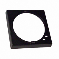
Y92P-48GB
Description
PNL CVR BLACK
Manufacturer
Omron
Series
H3CR-Gr
Type
Protective Coversr
Specifications of Y92P-48GB
Accessory Type
Cover, Panel
Color
Black
Lead Free Status / RoHS Status
Lead free / RoHS Compliant
For Use With/related Products
H3CR-G Series
Lead Free Status / Rohs Status
Lead free / RoHS Compliant
Other names
Y92P48GB
Z929
Z929


■ Characteristics
Note: For setting the time-limit of the Timer to a cycle of less than 3 seconds or applying the forced reset, use the H3BA-N in mode D (signal OFF-
Nomenclature
H3BA-N
4
Output Indicator (Orange):
Accuracy of operating time
Setting error
Reset time
Influence of voltage
Influence of temperature
Insulation resistance
Dielectric strength
Impulse withstand voltage
Noise immunity
Static immunity
Vibration resistance
Shock resistance
Ambient temperature
Ambient humidity
Life expectancy
Case color
Enclosure ratings
Weight
Lit when Timer outputs.
Time Range Selector:
delay).
1.2, 3, 12, and 30.
Select one from
Solid-state Timer
Item
Power Indicator (Green):
Lit when Timer operates.
Time setting knob (set time)
UP
PW
0.5
H3BA
0
1
sec
1.5
H3BA-N
± 0.3% FS max. ( ± 0.3% ± 10 ms in a range of 1.2 s)
± 5% FS ± 0.05 s max.
Min. power-opening time: 0.1 s max.
Min. pulse-input time:
± 0.5% FS max. ( ± 0.5% ± 10 ms in a range of 1.2 s)
± 2% FS max. ( ± 2% ± 10 ms in a range of 1.2 s)
100 M Ω min. (at 500 VDC)
2,000 VAC, 50/60 Hz for 1 min between current-carrying metal parts and exposed non-current-carrying metal
parts
2,000 VAC, 50/60 Hz for 1 min between control output terminals and operating circuit
1,000 VAC, 50/60 Hz for 1 min between contacts not located next to each other (750 VAC for H3BA-N8H)
1 kV (between power terminals)
2 kV (between current-carrying terminal and exposed non-current-carrying metal parts,
1.5 kV for 24-VDC models)
AC models: ± 1.5 kV (between power terminals), and ± 600 V (between input terminals),
DC models: ± 480 V (between power terminals), and ± 600 V (between input terminals),
Malfunction: 4 kV
Destruction: 8 kV
Destruction: 10 to 55 Hz with 0.75-mm single amplitude each in three directions
Malfunction: 10 to 55 Hz with 0.5-mm single amplitude each in three directions
Destruction: 1,000 m/s
Malfunction: 100 m/s
Operating: –10 ° C to 55 ° C (with no icing)
Storage:
Operating: 35% to 85%
Mechanical: 20 million operations min. (under no load
Electrical:
Light gray (Munsell 5Y7/1)
IEC: IP40 (panel surface)
Approx. 95 g
2
MODE
3
2.5
Operating Mode Display Window
A
square-wave noise by noise simulator (pulse width: 100 ns/1 µ s, 1-ns rise)
square-wave noise by noise simulator (pulse width: 100 ns/1 µ s, 1-ns rise)
–25 ° C to 65 ° C (with no icing)
at 1,800 operations/h)
100,000 operations min. (5 A at 250 VAC,
resistive load at 1,800 operations/h)
Operating Mode Selector:
Select a mode from
A, B, B2, C, D, and E
Scale Range Display
Windows
Time Unit Selector
Select a unit from
sec, min, hrs, and 10h.
2
H3BA-N
(approx. 10G) each in three directions
2
(approx. 100G) each in three directions
50 ms
Output Indicator (Orange):
H3BA-N8H
Lit when Timer outputs.
Time Range Selector:
1.2, 3, 12, and 30.
Select one from
Power Indicator (Green):
Lit when Timer operates.
Mechanical: 10 million operations min. (under no
Electrical:
Time setting knob (set time)
UP
PW
0.5
H3BA
load at 1,800 operations/h)
100,000 operations min. (5 A at 250
VAC, resistive load at 360 operations/h)
0
1
sec
1.5
H3BA-N8H
2
MODE
3
2.5
Output Type Display Window
A
Time Unit Selector
Select a unit from sec,
min, hrs, and 10 h.
Output Type Selector:
Select a type from A
and H
A: Time-limit DPDT
H: Time-limit SPDT and
Scale Range Display
Windows
(default setting)
instantaneous SPDT
Related parts for Y92P-48GB
Image
Part Number
Description
Manufacturer
Datasheet
Request
R

Part Number:
Description:
Mounting Hardware Front Panels - Rplc Black (N1.5)
Manufacturer:
Omron
Datasheet:
Part Number:
Description:
Mounting Hardware Front Panels - Rplc White (5Y9.2 / 0.5)
Manufacturer:
Omron
Datasheet:
Part Number:
Description:
Mounting Hardware Front Panels - Rplc Light gray (5Y7/1)
Manufacturer:
Omron
Datasheet:

Part Number:
Description:
PNL CVR LITE GRAY
Manufacturer:
Omron
Datasheet:
Part Number:
Description:
PNL CVR MED GRAY
Manufacturer:
Omron
Datasheet:

Part Number:
Description:
G6S-2GLow Signal Relay
Manufacturer:
Omron Corporation
Datasheet:
Part Number:
Description:
Compact, Low-cost, SSR Switching 5 to 20 A
Manufacturer:
Omron Corporation
Datasheet:
Part Number:
Description:
Manufacturer:
Omron Corporation
Datasheet:
Part Number:
Description:
Manufacturer:
Omron Corporation
Datasheet:
Part Number:
Description:
Manufacturer:
Omron Corporation
Datasheet:
Part Number:
Description:
Manufacturer:
Omron Corporation
Datasheet: