Y92P-48GB Omron, Y92P-48GB Datasheet - Page 17
Y92P-48GB
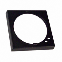
Manufacturer Part Number
Y92P-48GB
Description
PNL CVR BLACK
Manufacturer
Omron
Series
H3CR-Gr
Type
Protective Coversr
Specifications of Y92P-48GB
Accessory Type
Cover, Panel
Color
Black
Lead Free Status / RoHS Status
Lead free / RoHS Compliant
For Use With/related Products
H3CR-G Series
Lead Free Status / Rohs Status
Lead free / RoHS Compliant
Other names
Y92P48GB
Z929
Z929


Operating Time Setting
When setting the operating time, do not turn the setting knob beyond
its scale range. For precise time setting, conduct operation tests by
adjusting the setting knob.
The accuracy of the operating time of the Analog Timer is indicated
by the percentage value on the basis of the full-scale time. The
absolute fluctuation value will not be improved by changing the time
setting. Therefore, when selecting the model, be sure that the
application will be able to use a time setting as close as the full-scale
time setting of the Timer.
Others
When conducting a dielectric test, impulse voltage test, or insulation
resistance test between the electric circuit and non-current-carrying
metal parts of the Timer mounted to a control panel, be sure to take
the following steps. These steps will prevent the internal circuitry of
the Timer from damage that may be caused if a machine on the
control panel has an improper dielectric strength or insulation
resistance.
1. Separate the Timer from the circuitry of the control panel by
2. Short-circuit all terminals of the Timer.
Before using the Timer to switch inductive loads, be sure to connect
a surge absorbing element to the Timer in order to prevent the Timer
from malfunction and damage. A diode is an example of a surge
absorbing element for DC circuits and a surge absorber is an
example of a surge absorbing element for AC circuits.
Do not leave the Timer in time-up condition for a month or longer in
places with high temperatures, otherwise the internal parts, such as
an electrolytic capacitor, of the Timer may be damaged. Use the
Timer with an appropriate relay so that the Timer will not be left in
time-up condition for a long time.
If the Timer is mounted in contact with a mounting surface, the
service life of internal parts may be shortened. Provide at least 10
mm between the Timer and the mounting surface to prolong the
service life of the Timer.
When the Timer is reset right after the Timer goes into time-up
condition, be sure to provide the Timer with an appropriate circuit
configuration considering the resetting time of the Timer so that a
sequential error will not result.
The Timer uses the constant value read method. Be careful when
changing the set value because the output of the Timer will be ON
when the set value coincides with the count value.
Be sure that the casing of the Timer is free from organic solvents,
such as paint thinner and benzene, strong acid, and alkali solvents,
which will damage the casing.
Note: It is impossible to connect more than two Timers in parallel.
disconnecting the socket from the Timer or wires.
If any device with no-contact output, such as a proximity sensor,
photoelectric sensor, or SSR, is directly connected to the Timer,
current leakage from the device may cause Timer malfunction. Be
sure to test the device with the Timer before using the device for
actual applications.
■ Mounting
Surface Mounting
There is no particular restriction on surface mounting directions, but
be sure that the Timer is securely mounted horizontally.
P2CF Socket
When mounting the Timer vertically with the P2CF Socket, consider
the movable hooks and be sure that there is a 20-mm space on each
of the upper and lower parts of the Socket.
Solid-state Timer
Hook
Duct
Panel
H3BA-N
P2CF-08
17
Related parts for Y92P-48GB
Image
Part Number
Description
Manufacturer
Datasheet
Request
R

Part Number:
Description:
Mounting Hardware Front Panels - Rplc Black (N1.5)
Manufacturer:
Omron
Datasheet:
Part Number:
Description:
Mounting Hardware Front Panels - Rplc White (5Y9.2 / 0.5)
Manufacturer:
Omron
Datasheet:
Part Number:
Description:
Mounting Hardware Front Panels - Rplc Light gray (5Y7/1)
Manufacturer:
Omron
Datasheet:

Part Number:
Description:
PNL CVR LITE GRAY
Manufacturer:
Omron
Datasheet:
Part Number:
Description:
PNL CVR MED GRAY
Manufacturer:
Omron
Datasheet:

Part Number:
Description:
G6S-2GLow Signal Relay
Manufacturer:
Omron Corporation
Datasheet:
Part Number:
Description:
Compact, Low-cost, SSR Switching 5 to 20 A
Manufacturer:
Omron Corporation
Datasheet:
Part Number:
Description:
Manufacturer:
Omron Corporation
Datasheet:
Part Number:
Description:
Manufacturer:
Omron Corporation
Datasheet:
Part Number:
Description:
Manufacturer:
Omron Corporation
Datasheet:
Part Number:
Description:
Manufacturer:
Omron Corporation
Datasheet: