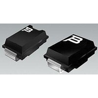
TISP4360M3BJR Bourns Inc., TISP4360M3BJR Datasheet - Page 8

TISP4360M3BJR
Manufacturer Part Number
TISP4360M3BJR
Description
Sidacs
Manufacturer
Bourns Inc.
Datasheet
1.TISP4360MMBJR.pdf
(16 pages)
Specifications of TISP4360M3BJR
Breakover Current Ibo Max
32 A
Rated Repetitive Off-state Voltage Vdrm
290 V
Off-state Leakage Current @ Vdrm Idrm
0.005 mA
Forward Voltage Drop
3 V
Mounting Style
SMD/SMT
Package / Case
DO-214AA
Lead Free Status / RoHS Status
Lead free / RoHS Compliant
Available stocks
Company
Part Number
Manufacturer
Quantity
Price
Company:
Part Number:
TISP4360M3BJR-S
Manufacturer:
BOURNS
Quantity:
240 000
Company:
Part Number:
TISP4360M3BJR-S
Manufacturer:
TI
Quantity:
2 247
From 2001, the registrations for FCC equipment changed from the FCC to ACTA, Administrative Council for Terminal Attachments. For this
function, ACTA needed to adopt a US National standard specifying terminal equipment requirements. The TIA, Telecommunications
Industry Association, in conjunction with the EIA, Electronic Industries Alliance, created TIA/EIA-IS-968 for this purpose. The first issue of
TIA/EIA-IS-968 is essentially a renumbered version of the FCC Part 68 requirement. Clause and figure changes are shown in the table.
To verify the withstand capability and safety of the equipment, standards require that the equipment is tested with various impulse wave forms.
The table below shows values for the TIA/EIA-IS-968 and ITU-T recommendation K.21.
If the impulse generator current exceeds the protector’s current rating then a series resistance can be used to reduce the current to the
protector’s rated value to prevent possible failure. For the new edition of ITU-T recommendation K.21 (2000) some series resistance might
be needed to pass the impulse coordination test. The value for a 400 V primary protector is given in the table.
The required value of device survival series resistance for a given waveform is given by the following calculations. First, the minimum total
circuit impedance is found by dividing the impulse generator’s peak voltage by the protector’s rated current. The impulse generator’s fictive
impedance (generator’s peak voltage divided by peak short circuit current) is then subtracted from the minimum total circuit impedance to
give the required value of series resistance.
For the TIA/EIA-IS-968 10/560 waveform the following values result. The minimum total circuit impedance is 800/55 = 15 Ω and the
generator’s fictive impedance is 800/100 = 8 Ω. For an inter-conductor connected TISP43xxMM, this gives a minimum series resistance value
of 15 - 8 = 7 Ω. The 10/160 waveform only needs to be considered if the TISP43xxMM is connected from the conductor to ground. In this
case the conductor series resistance is 12.5 Ω per conductor.
Fuses must not operate on the Type B surge. To survive a 37.5 A Type B surge, the fuse needs to have a melting I
To survive the Type A surges a fuse melting I
does not operate on Type B surges (I
Type A testing.
FCC Part 68, ACTA, TIA and EIA
TIA/EIA-IS-968 (FCC Part 68) Impulse Testing
Fuse Values for TIA/EIA-IS-968 (FCC Part 68)
TIA/EIA-IS-968
ITU-T K.21 ‡
Basic Level
ITU-T K.21 ‡
Enhanced Level
† TIA/EIA-IS-968 terminology for the wave forms produced by the ITU-T recommendation K.21 10/700 impulse generator
‡ Values assume the TISP43xxMM is connected inter-conductor and a 400 V primary is used
(F CC Part 68)
TISP43xxMMAJ/BJ Overvoltage Protector Series
Standard
Longitudinal
Longitudinal
Transverse
Transverse
Condition
Metallic
Metallic
Test
V
Telephone Line Surge – Type A
Telephone Line Surge – Type B
Simplified Surge Generator
Open Circuit voltage Wave shape
Short Circuit Current Wave shape
2
t > 0.7 A
Voltage
1500
1500
Peak
1000
1500
4000
1500
6000
800
2
V
t value of greater than 10 A
2
s) and does operate on Type A surges (I
Item
Wave Form
APPLICATIONS INFORMATION
9/720 †
Voltage
9/720 †
10/700
10/700
10/160
10/560
µs
Current
Peak
37.5
37.5
37.5
200
100
100
125
25
A
Clause 68.302 (b)
Clause 68.302 (c)
2
Fig. 68.302 (c)
Fig. 68.302 (a)
Fig. 68.302 (b)
FCC Part 68
s for 10/160 and 8 A
Wave Form
Customers should verify actual device performance in their specific applications.
Current
5/320 †
5/320 †
10/160
10/560
5/310
5/310
µs
2
t < 8 A
TIA/EIA-IS-968
Clause 4.2.3
Clause 4.2.2
Impedance
2
Figure 4.2
Figure 4.3
Figure 4.1
2
s for 10/560 is needed. By using a fuse which
s) a non-operational pass can be achieved for
Fictive
7.5
40
40
40
40
8
Ω
Specifications are subject to change without notice.
NOVEMBER 2001 - REVISED JANUARY 2007
TISP43xxMM
Rating
2
65
65
75
55
65
65
t of greater than 0.7 A
A
Resista nce
2 x 13
Series
6.6
6.2
0
0
0
Ω
7
0
2
s.


