DSEK60-02A IXYS, DSEK60-02A Datasheet
DSEK60-02A
Manufacturer Part Number
DSEK60-02A
Description
DIODE FRED 200V 34A TO-247AD
Manufacturer
IXYS
Datasheet
1.DSEK60-02A.pdf
(2 pages)
Specifications of DSEK60-02A
Voltage - Forward (vf) (max) @ If
1.1V @ 30A
Current - Reverse Leakage @ Vr
200µA @ 200V
Current - Average Rectified (io) (per Diode)
34A
Voltage - Dc Reverse (vr) (max)
200V
Reverse Recovery Time (trr)
50ns
Diode Type
Standard
Speed
Fast Recovery =< 500ns, > 200mA (Io)
Diode Configuration
1 Pair Common Cathode
Mounting Type
Through Hole, Radial
Package / Case
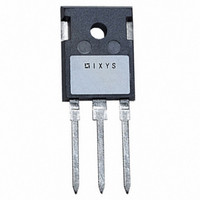
TO-247AD
Product
Fast Recovery Rectifier
Configuration
Dual Common Cathode
Reverse Voltage
200 V
Forward Voltage Drop
1.1 V at 30 A
Recovery Time
50 ns
Forward Continuous Current
50 A
Max Surge Current
350 A
Reverse Current Ir
200 uA
Mounting Style
Through Hole
Maximum Operating Temperature
+ 150 C
Minimum Operating Temperature
- 40 C
Vrrm, (v)
200
Ifavm, D = 0.5, Total, (a)
68
Ifavm, D = 0.5, Per Diode, (a)
34
@ Tc, (°c)
115
Ifrms, (a)
50
Ifsm, 10 Ms, Tvj=45°c, (a)
325
Vf, Max, Tvj =150°c, (v)
0.85
@ If, (a)
30
Trr, Typ, Tvj =25°c, (ns)
35
Irm , Typ, Tvj =100°c, (a)
4.0
@ -di/dt, (a/µs)
100
Tvjm, (°c)
150
Rthjc, Max, (k/w)
1.00
Package Style
TO-247
Lead Free Status / RoHS Status
Lead free / RoHS Compliant
Available stocks
Company
Part Number
Manufacturer
Quantity
Price
Company:

Part Number:
DSEK60-02A
Manufacturer:
INFINEON
Quantity:
3 000
Part Number:
DSEK60-02A
Manufacturer:
IXYS/艾赛斯
Quantity:
20 000


© 1999 IXYS All rights reserved
Common Cathode
Fast Recovery
Epitaxial Diode (FRED)
Symbol
I
I
I
I
I
T
T
T
P
M
V
Weight
* Verson A only; ** Version AR only
Symbol
I
V
V
r
mΩ
R
R
t
I
Data according to IEC 60747 refer to a single diode unless otherwise stated.
IXYS reserves the right to change limits, test conditions and dimensions
FRMS
FAVM
FRM
FSM
2
R
RM
rr
V
T
200
200
t
VJ
VJM
stg
tot
T0
ISOL
F
thJC
thCH
d
RSM
V
I
*
FAVM
**
rating includes reverse blocking losses at T
T
T
T
I
For power-loss calculations only
T
I
V
L ≤ 0.05 µH; T
F
F
VJ
VJ
VJ
VJ
R
= 30 A;
= 1 A; -di/dt = 100 A/µs; V
V
200
200
= 100 V;
= 25°C
= 25°C
= 125°C
= T
RRM
V
T
T
t
T
T
T
T
T
Mounting torque with screw M3
Mounting torque with screw M3.5
50/60 Hz, RMS, t = 1 minute, leads-to-tab
Test Conditions
Test Conditions
P
VJ
C
VJ
VJ
VJ
VJ
C
VJM
< 10 µs; rep. rating, pulse width limited by T
= 115°C; rectangular, d = 0.5
= 25°C
= T
= 45°C;
= 150°C; t = 10 ms (50 Hz), sine
= 45°C
= 150°C; t = 10 ms (50 Hz), sine
VJM
V
V
V
T
T
I
VJ
F
VJ
VJ
R
R
R
= 30 A; -di
= 25°C
Type
DSEK 60-02A
DSEK 60-02AR
t = 10 ms (50 Hz), sine
t = 8.3 ms (60 Hz), sine
t = 8.3 ms (60 Hz), sine
t = 10 ms (50 Hz), sine
t = 8.3 ms (60 Hz), sine
t = 8.3 ms (60 Hz), sine
= V
= 0.8 • V
= 0.8 • V
= 150°C
=
RRM
25°C
F
/dt = 100 A/µs
RRM
RRM
R
= 30 V; T
VJM
, V
R
VJ
= 0.8 V
= 25°C
RRM
, duty cycle d = 0.5
VJM
Characteristic Values per leg
Maximum Ratings per leg
0.45-0.55/4-5
0.45-0.55/4-5
typ.
0.5
-40...+150
-40...+150
35
4
A
DSEK 60
375
325
350
290
310
530
510
420
400
150
125
50
34
max.
0.85
1.10
0.72
200
2500
4.2
6
50µA
50ns
5 mA
1 K/W
5 A
C
K/W
Nm/lb.in.
Nm/lb.in.
A
A
A
A
V~
°C
°C
°C
W
A
A
A
A
A
A
A
g
2
2
2
2
A
s
s
s
s
µA
V
V
V
I
V
t
TO-247 AD
Version A
A
A = Anode, C = Cathode
Features
Applications
Advantages
C
FAVM
A
rr
International standard package
JEDEC TO-247 AD
Planar passivated chips
Very short recovery time
Extremely low switching losses
Low I
Soft recovery behavior
Epoxy meets UL 94V-0 flammability
classification
Version AR isolated and
Rectifiers in switch mode power
supplies (SMPS)
Uninterruptible power supplies (UPS)
Ultrasonic cleaners and welders
High reliability circuit operation
Low voltage peaks for reduced
protection circuits
Low noise switching
Low losses
Operating at lower temperature or
space saving by reduced cooling
UL registered E153432
RRM
RM
-values
= 2x 34 A
= 200 V
= 35 ns
C (TAB)
A
C
ISOPLUS 247
A
Version AR
D1 - 35
TAB
TM
D1
Related parts for DSEK60-02A
Image
Part Number
Description
Manufacturer
Datasheet
Request
R

Part Number:
Description:
DIODE FRED 600V 2X30A TO-247AD
Manufacturer:
IXYS
Datasheet:
Part Number:
Description:
DIODE FRED 1200V 2X26A TO-247
Manufacturer:
IXYS
Datasheet:

Part Number:
Description:
DIODE FRED 200V 34A ISOPLUS247
Manufacturer:
IXYS
Datasheet:

Part Number:
Description:
Common Cathode Fast Recovery Epitaxial Diode (FRED)
Manufacturer:
IXYS Corporation

Part Number:
Description:
HiPerFET Power MOSFETs
Manufacturer:
IXYS Corporation
Datasheet:
Part Number:
Description:
J-K-Type Flip-Flop
Manufacturer:
IXYS Corporation
Datasheet:
Part Number:
Description:
HiPerRF Power MOSFETs
Manufacturer:
IXYS Corporation
Datasheet:
Part Number:
Description:
Rectifier Module for Three Phase Power Factor Correction
Manufacturer:
IXYS Corporation
Datasheet:
Part Number:
Description:
Thyristor Modules Thyristor/Diode Modules
Manufacturer:
IXYS Corporation
Datasheet:
Part Number:
Description:
Thyristor Modules Thyristor/Diode Modules
Manufacturer:
IXYS Corporation
Datasheet:
DSEK60-02A Summary of contents
Page 1
... VJ I rating includes reverse blocking losses at T FAVM Data according to IEC 60747 refer to a single diode unless otherwise stated. IXYS reserves the right to change limits, test conditions and dimensions © 1999 IXYS All rights reserved DSEK Maximum Ratings per leg ...
Page 2
... T VJ Fig. 4 Dynamic parameters versus T VJ 1.2 K/W 1.0 0.8 Z thJC 0.6 0.4 0.2 0.0 0.001 0.01 0.1 Fig. 7 Transient thermal impedance junction to case © 1999 IXYS All rights reserved 0 100° 100V µ 0 15A F 0 35A 70A F 0.2 0.0 10 100 A/µ ...