IRKT162/12PBF Vishay, IRKT162/12PBF Datasheet - Page 3
IRKT162/12PBF
Manufacturer Part Number
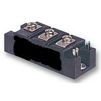
IRKT162/12PBF
Description
SCR Modules 1200 Volt 160 Amp
Manufacturer
Vishay
Datasheet
1.IRKT16212PBF.pdf
(8 pages)
Specifications of IRKT162/12PBF
Mounting Style
Screw
Peak Repetitive Off-state Voltage, Vdrm
1200V
Gate Trigger Current Max, Igt
150mA
Current It Av
160A
On State Rms Current It(rms)
355A
Holding Current Max Ih
200mA
Gate Trigger Voltage Max
RoHS Compliant
Lead Free Status / RoHS Status
Lead free / RoHS Compliant


Note
• Table shows the increment of thermal resistance R
Document Number: 94632
Revision: 08-Dec-08
TRIGGERING
PARAMETER
Maximum peak gate power
Maximum average gate power
Maximum peak gate current
Maximum peak negative gate voltage
Maximum gate voltage required to trigger
Maximum gate current required to trigger
Maximum gate voltage that will not trigger
Maximum gate current that will not trigger
BLOCKING
PARAMETER
Maximum peak reverse and off-state
leakage current at V
RMS insulation voltage
Maximum critical rate of rise of off-state voltage
THERMAL AND MECHANICAL SPECIFICATIONS
PARAMETER
Junction operating and storage
temperature range
Maximum internal thermal resistance,
junction to case per leg
Typical thermal resistance,
case to heatsink per module
Mounting torque ± 10 %
Approximate weight
Case style
ΔR CONDUCTION PER JUNCTION
DEVICES
VSK.91..
180°
0.04
RRM
Thyristor/Diode and Thyristor/Thyristor, 95 A
ADD-A-PAK Generation VII Power Modules
, V
SINE HALF WAVE CONDUCTION
DRM
0.048
120°
to heatsink
busbar
For technical questions, contact: ind-modules@vishay.com
0.063
90°
SYMBOL
SYMBOL
SYMBOL
T
P
- V
dV/dt
I
R
R
I
V
J
thJC
P
V
V
RRM,
I
DRM
G(AV)
I
I
, T
GM
GD
0.085
GT
thCS
INS
thJC
GM
GD
GT
GM
60°
Stg
when devices operate at different conduction angles than DC
T
50 Hz, 1 s
T
T
T
T
T
T
T
T
T
DC operation
Mounting surface flat, smooth and greased
A mounting compound is recommended and the
torque should be rechecked after a period of
3 hours to allow for the spread of the compound.
JEDEC
J
J
J
J
J
J
J
J
J
J
0.125
= - 40 °C
= 25 °C
= 125 °C
= - 40 °C
= 25 °C
= 125 °C
= 125 °C, rated V
= 125 °C, rated V
= 125 °C, gate open circuit
= 125 °C, linear to 0.67 V
30°
0.033
TEST CONDITIONS
TEST CONDITIONS
TEST CONDITIONS
180°
RECTANGULAR WAVE CONDUCTION
DRM
DRM
applied
applied
0.052
120°
Anode supply = 6 V
resistive load
Anode supply = 6 V
resistive load
DRM
Vishay High Power Products
0.067
90°
VSK.91.. Series
0.088
60°
- 40 to 125
VALUES
VALUES
VALUES
TO-240AA compatible
3500
1000
0.22
0.25
270
150
0.1
2.7
3.0
3.0
4.0
2.5
1.7
15
75
12
10
80
4
3
6
0.127
30°
www.vishay.com
UNITS
UNITS
UNITS
°C/W
V/µs
mA
mA
mA
Nm
oz.
°C
W
UNITS
A
V
V
V
g
°C/W
3
Related parts for IRKT162/12PBF
Image
Part Number
Description
Manufacturer
Datasheet
Request
R

Part Number:
Description:
SCR DBL HISCR 800V 160A INTAPAK
Manufacturer:
Vishay
Datasheet:
Part Number:
Description:
SCR DBL HISCR 1200V 160A INTAPAK
Manufacturer:
Vishay
Datasheet:
Part Number:
Description:
SCR DBL HISCR 1600V 160A INTAPAK
Manufacturer:
Vishay
Datasheet:
Part Number:
Description:
SCR DBL HISCR 1400V 160A INTAPAK
Manufacturer:
Vishay
Datasheet:
Part Number:
Description:
SCR DBL HISCR 400V 160A INTAPAK
Manufacturer:
Vishay
Datasheet:
Part Number:
Description:
357-036-542-201 CARDEDGE 36POS DL .156 BLK LOPRO
Manufacturer:
Vishay
Datasheet:
Part Number:
Description:
357-036-542-201 CARDEDGE 36POS DL .156 BLK LOPRO
Manufacturer:
Vishay
Datasheet:
Part Number:
Description:
357-036-542-201 CARDEDGE 36POS DL .156 BLK LOPRO
Manufacturer:
Vishay
Datasheet:
Part Number:
Description:
357-036-542-201 CARDEDGE 36POS DL .156 BLK LOPRO
Manufacturer:
Vishay
Datasheet:
Part Number:
Description:
357-036-542-201 CARDEDGE 36POS DL .156 BLK LOPRO
Manufacturer:
Vishay
Datasheet:
Part Number:
Description:
357-036-542-201 CARDEDGE 36POS DL .156 BLK LOPRO
Manufacturer:
Vishay
Datasheet: