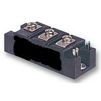
IRKT162/12PBF Vishay, IRKT162/12PBF Datasheet

IRKT162/12PBF
Specifications of IRKT162/12PBF
Related parts for IRKT162/12PBF
IRKT162/12PBF Summary of contents
Page 1
... UPS and battery charger. CHARACTERISTICS 400 to 1600 - 40 to 125 For technical questions, contact: ind-modules@vishay.com VSK.91.. Series Vishay High Power Products isolating voltage RMS VALUES UNITS ...
Page 2
... TM T(AV °C, anode supply = resistive load, gate open circuit °C, anode supply = 6 V, resistive load T(RMS) For technical questions, contact: ind-modules@vishay.com V , MAXIMUM REPETITIVE DRM PEAK OFF-STATE VOLTAGE, GATE OPEN CIRCUIT V 400 600 800 1000 1200 1400 1600 VALUES 95 or 210 ...
Page 3
... RECTANGULAR WAVE CONDUCTION 90° 60° 30° 180° 0.063 0.085 0.125 0.033 when devices operate at different conduction angles than DC thJC For technical questions, contact: ind-modules@vishay.com VSK.91.. Series Vishay High Power Products VALUES 12 3.0 3.0 10 4.0 Anode supply = 6 V 2.5 resistive load 1 ...
Page 4
... Average on-state current (A) Fig On-State Power Loss Characteristics www.vishay.com 4 ADD-A-PAK Generation VII Power Modules Thyristor/Diode and Thyristor/Thyristor 100 80 100 For technical questions, contact: ind-modules@vishay.com 220 180° 200 120° 180 90° 60° 160 DC 30° 140 120 RMS limit 100 ...
Page 5
... Maximum allowable ambient temperature (°C) Total output current (A) Fig On-State Power Loss Characteristics For technical questions, contact: ind-modules@vishay.com VSK.91.. Series Vishay High Power Products RthSA = 0.1 °C/W 0.2 °C/W 0.3 °C/W 0.5 °C/W 0.7 °C/W 1 °C/W 1.5 ° ...
Page 6
... Square wave pulse duration (s) Fig Thermal Impedance Z thJC (a) (b) IGD IR K.71../ .91.. S eries VSK. F requenc y Limited by PG(AV) 0.01 0.1 1 Instantaneous gate current (A) Fig Gate Characteristics For technical questions, contact: ind-modules@vishay.com 3.0 3 Characteristics (1) PGM = 200 300 µs (2) PGM = (3) PGM = (4) PGM = (4) (3) (2) (1) 10 ...
Page 7
... ADD-A-PAK Generation VII Power Modules Thyristor/Diode and Thyristor/Thyristor ORDERING INFORMATION TABLE Device code Note • To order the optional hardware go to www.vishay.com/doc?95172 CIRCUIT CONFIGURATION VSKT ( ( ( (4) (5) (7) (6) Dimensions Document Number: 94632 Revision: 08-Dec-08 VSK Module type 2 - Circuit configuration (see end of datasheet Current code (95 A) ...
Page 8
... Vishay disclaims any and all liability arising out of the use or application of any product described herein or of any information provided herein to the maximum extent permitted by law. The product specifications do not expand or otherwise modify Vishay’ ...


