MT9M413C36STM Aptina LLC, MT9M413C36STM Datasheet - Page 5
MT9M413C36STM
Manufacturer Part Number
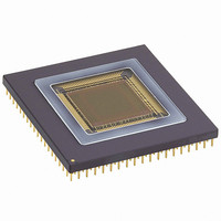
MT9M413C36STM
Description
SENSOR IMAGE MONO CMOS 280-PGA
Manufacturer
Aptina LLC
Type
CMOS Imagingr
Specifications of MT9M413C36STM
Pixel Size
12µm x 12µm
Active Pixel Array
1280H x 1024V
Frames Per Second
500
Voltage - Supply
3.3V
Package / Case
280-PGA
Sensor Image Color Type
Monochrome
Sensor Image Size
1280x1024Pixels
Operating Supply Voltage (min)
3V
Operating Supply Voltage (max)
3.6V
Operating Temp Range
-5C to 60C
Package Type
CPGA
Operating Temperature Classification
Commercial
Mounting
Through Hole
Pin Count
280
Lead Free Status / RoHS Status
Contains lead / RoHS non-compliant
Other names
557-1153


External Control Sequence
circuitry to control most of the pixel, ADC, and output
multiplexing operations. However, the sensor still
requires a controller (FPGA, CPLD, ASIC, etc.) to guide
it through the full sequence of its operation.
signal charges are integrated in all pixels in parallel.
The charges are then sampled into pixel analog memo-
ries (one memory per pixel) and subsequently, row by
row, are digitized and read out of the sensor. The inte-
gration of photosignal is controlled by two control sig-
nals: PG_N and TX_N. To clear pixels and start new
integration, PG_N is made low. To transfer the data
into pixel memory, TX_N is made low. The time differ-
ence between the two procedures is the exposure time.
It should be noted that neither the PG_N or TX_N
pulses clear the pixel analog memory. Pixel memory
can be cleared during the previous readout (i.e., the
readout process resets the pixel analog memory), or by
applying PG_N and TX_N together (i.e., clearing both
pixel and pixel memory at the same time).
the sensor can operate in either simultaneous or
sequential mode in which it generates continuous
video output. In simultaneous mode, as a series of
frames are being captured, the PG_N and TX_N signals
are exercised while the previous frame is being read
out of the sensor. In simultaneous mode typically the
end of integration occurs in the last row of the frame
(row #1023) or in the last row of the window of interest.
The position of the start integration is then calculated
from the desired integration time. In sequential mode
the PG_N and TX_N signals are exercised to control the
integration time, and then digitization and readout of
the frame takes place. Alternatively, the sensor can run
in single frame or snapshot mode in which one image
is captured.
that allows the array of 1,280 analog-to-digital convert-
ers on the chip to digitize simultaneously the analog
data from an entire pixel row. The following input sig-
nals are utilized to control the conversion and readout
process:
09005aef806807ca
MT9M413C36STC.fm - Ver. 3.0 1/04 EN
The MI-MV13 includes on-chip timing and control
With the TrueSNAP freeze-frame electronic shutter
With the TrueSNAP freeze-frame electronic shutter
The sensor has a column-parallel ADC architecture
1.3-MEGAPIXEL CMOS ACTIVE-PIXEL
5
Table 1:
selects the pixel row to be read for each readout cycle.
The ROW_STRT_N signal starts the process of reading
the analog data from the pixel row, the analog-to-digi-
tal conversion, and the storage of the digital values in
the ADC registers. When these actions are completed,
the sensor sends a response back to the system con-
troller using the ROW_DONE_N. Row address must be
valid for the first half of the row processing time (the
period between ROW_START_N and ROW_DONE_N).
array, which is used to store the data after digitization.
This memory also allows the data from the previous
row conversion cycle to be read while a new conver-
sion is taking place.
LD_SHFT_N
DATA_READ_EN_N signal. LD_SHFT_N transfers the
digitized data from the ADC register to the output reg-
ister. DATA_READ_EN_N is used to enable the data
output from the output register. A new pixel row read-
out and conversion cycle can be started two clock
cycles after DATA_READ_EN_N is pulled low. The out-
put register allows the reading of the digital data from
the previous row to be performed at the same time as a
new conversion (pipeline mode). This means that the
total row time will be only that between when: (a) the
ROW_STRT_N signal is applied and ROW_DONE_N is
returned; and (b) LD_SHFT_N and DATA_READ_EN_N
are applied plus two clock cycles. The pipelined opera-
tion means there will always be 1 row of latency at the
start of sensor operation. The alternative to pipelined
operation is burst data operation in which a new pixel
row conversion is not initiated until after the output
register is emptied (and LD_SHFT_N has been taken
high). The ratio of line active and blanking times can
be adjusted to easily match a variety of display and
collection formats. See “Timing Diagram For One
Row” on page 7.
SIGNAL NAME
ROW_ADDR
ROW_STRT_N
LD_SHFT_N
DATA_READ_EN_N
The 10-bit ROW_ADDR (row address) input bus
The MI-MV13 contains a pipeline style memory
The digital readout is controlled by lowering the
Micron Technology, Inc., reserves the right to change products or specifications without notice.
DIGITAL IMAGE SENSOR
Conversion and Readout
Process
signal,
DESCRIPTION
Row Address
Row Start
Load shift register 1-bit
Data read enable
©2004 Micron Technology, Inc. All rights reserved.
followed
INPUT BUS
WIDTH
10-bit
1-bit
1-bit
by
the
Related parts for MT9M413C36STM
Image
Part Number
Description
Manufacturer
Datasheet
Request
R

Part Number:
Description:
SENSOR IMAGE VGA COLOR CMOS PLCC
Manufacturer:
Aptina LLC
Datasheet:

Part Number:
Description:
IC SENSOR IMAGE COLOR 48CLCC
Manufacturer:
Aptina LLC
Datasheet:

Part Number:
Description:
SENSOR IMAGE 1.3MP CMOS 48-CLCC
Manufacturer:
Aptina LLC
Datasheet:

Part Number:
Description:
SENSOR IMAGE 2MP CMOS 48-CLCC
Manufacturer:
Aptina LLC
Datasheet:

Part Number:
Description:
SENSOR IMAGE VGA MONO 52IBGA
Manufacturer:
Aptina LLC
Datasheet:

Part Number:
Description:
SENSOR IMAGE VGA COLOR 48CLCC
Manufacturer:
Aptina LLC
Datasheet:

Part Number:
Description:
SENSOR IMAGE COLOR CMOS 48-PLCC
Manufacturer:
Aptina LLC
Datasheet:

Part Number:
Description:
KIT HEAD BOARD FOR MT9P031
Manufacturer:
Aptina LLC
Datasheet:

Part Number:
Description:
KIT HEAD BOARD FOR MT9D131
Manufacturer:
Aptina LLC
Datasheet:

Part Number:
Description:
KIT HEAD BOARD FOR MT9P031
Manufacturer:
Aptina LLC
Datasheet:
Part Number:
Description:
SENSOR IMAGE VGA COLOR CMOS PLCC
Manufacturer:
Aptina LLC
Datasheet:
Part Number:
Description:
IC SENSOR IMAGE COLOR 48CLCC
Manufacturer:
Aptina LLC
Datasheet:
Part Number:
Description:
SENSOR IMAGE 2MP CMOS 48-CLCC
Manufacturer:
Aptina LLC
Datasheet:
