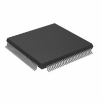
ADV611JSTZ Analog Devices Inc, ADV611JSTZ Datasheet - Page 13

ADV611JSTZ
Manufacturer Part Number
ADV611JSTZ
Description
CCTV Digital Video Codec
Manufacturer
Analog Devices Inc
Type
Video Codecr
Datasheet
1.ADV611JSTZ.pdf
(46 pages)
Specifications of ADV611JSTZ
Data Interface
Serial
Resolution (bits)
8 b
Sigma Delta
No
Voltage - Supply, Digital
4.5 V ~ 5.5 V
Operating Temperature
0°C ~ 70°C
Mounting Type
Surface Mount
Package / Case
120-LQFP
Lead Free Status / RoHS Status
Lead free / RoHS Compliant
Available stocks
Company
Part Number
Manufacturer
Quantity
Price
Company:
Part Number:
ADV611JSTZ
Manufacturer:
ADI
Quantity:
526
Company:
Part Number:
ADV611JSTZ
Manufacturer:
Analog Devices Inc
Quantity:
10 000
Part Number:
ADV611JSTZ
Manufacturer:
ADI
Quantity:
20 000
[7]
[8]
[9]
[10]
[11]
[12]
[13]
[14]
[15]
FIFO Control Register
Indirect (Read/Write) Register Index 0x01
This register holds the service-request settings for the ADV611/ADV612’s host interface FIFO, causing interrupts for the “nearly full” and
“nearly empty” levels. Because each register is four bits in size, and the FIFO is 512 positions, the 4-bit value must be multiplied by 32
(decimal) to determine the exact value for encode service level (nearly full) and decode service level (nearly empty). The ADV611/ADV612
uses these settings to determine when to generate a FIFO Service Request related host interrupt (FIFOSRQ bit and FIFO_SRQ pin).
[3:0]
[15:8]
REV. 0
[7:4]
Video Interface Encode/Decode Mode Select, E/D. This bit selects the following:
0
1
Reserved (always write zero)
Video Interface Bipolar/Unipolar Color Component Select, BUC. This bit selects the following:
0
1
Reserved (always write zero)
Video Interface Software Reset, SWR. This bit has the following effects on ADV611/ADV612 operations:
0
1
HSYNC pin Polarity, PHSYNC. This bit has the following effects on ADV611/ADV612 operations:
0
1
HIRQ pin Polarity, PHIRQ. This bit has the following effects on ADV611/ADV612 operations:
0
1
Quality Box Enable, QBE. This bit has the following effect on ADV611/ADV612 operations:
0
1
Video Stall Enable, VSE. This bit has the following effect on ADV611/ADV612 operations:
0
1
Encode Service Level, ESL[3:0]. The value in this field determines when the FIFO is considered nearly full on encode; a condi-
tion that generates a FIFO service request condition in encode mode. Since this register is four bits (16 states), and the FIFO is
512 positions, the step size for each bit in this register is 32 positions. The following table summarizes sample states of the
register and their meaning.
ESL Interrupt When . . .
0000 Disables service requests (FIFO_SRQ never goes HI during encode)
0001 FIFO has only 32 positions filled (FIFO_SRQ when >= 32 positions are filled)
1000 FIFO is 1/2 full, reset value
1111 FIFO has only 32 positions empty (480 positions filled)
Decode Service Level, DSL[7:4]. The value in this field determines when the FIFO is considered nearly empty in decode; a
condition that generates a FIFO service request in decode mode. Because this register is four bits (16 states), and the FIFO
is 512 positions, the step size for each bit in this register is 32 positions. The following table summarizes sample states of the
register and their meaning.
DSL Interrupt When . . .
0000 Disables service requests (FIFO_SRQ never goes HI)
0001 FIFO has only 32 positions filled (480 positions empty)
1000 FIFO is 1/2 empty, reset value
1111 FIFO has only 32 positions empty (FIFO_SRQ when >= 32 positions are empty)
Reserved (always write zero)
Decode mode video interface (compressed-to-raw)
Encode mode video interface (raw-to-compressed), reset value
Bipolar color component mode video interface, reset value
Unipolar color component mode video interface
Normal operation
Software Reset. This bit is set on hardware reset and must be cleared before the ADV611/ADV612 can begin processing.
(reset value)
When this bit is set during encode, the ADV611/ADV612 completes processing the current field then suspends operation
until the SWR bit is cleared. When this bit is set during decode, the ADV611/ADV612 suspends operation immediately and
does not resume operation until the SWR bit is cleared. Note that this bit must be set whenever any other bit in the Mode
register is changed.
HSYNC is HI during blanking, reset value
HSYNC is LO during blanking (HI during active)
HIRQ is active LO, reset value
HIRQ is active HI
Video area registers (HSTART, HEND, VSTART, VEND). Crop video area, setting cropped area to all 0
quantizations (ADV601 mode), reset value
Video area registers (HSTART, HEND, VSTART, VEND). Select Quality Box. Quantization of the area outside
the box is selected with the background Contrast Control register. See the video area registers for more information
on the Quality Box.
Video Stall disabled (ADV601 mode), reset value
Video Stall enabled.
–13–
ADV611/ADV612


