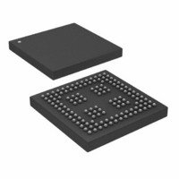
ADSP-21261SKBCZ150 Analog Devices Inc, ADSP-21261SKBCZ150 Datasheet - Page 38

ADSP-21261SKBCZ150
Manufacturer Part Number
ADSP-21261SKBCZ150
Description
150 MHz, 32Bit DSP Processor
Manufacturer
Analog Devices Inc
Series
SHARC®r
Type
Fixed/Floating Pointr
Specifications of ADSP-21261SKBCZ150
Interface
DAI, SPI
Clock Rate
150MHz
Non-volatile Memory
ROM (384 kB)
On-chip Ram
128kB
Voltage - I/o
3.30V
Voltage - Core
1.20V
Operating Temperature
0°C ~ 70°C
Mounting Type
Surface Mount
Package / Case
136-CSPBGA
Device Core Size
32/40Bit
Architecture
Super Harvard
Format
Floating Point
Clock Freq (max)
150MHz
Mips
150
Device Input Clock Speed
150MHz
Ram Size
128KB
Program Memory Size
384KB
Operating Supply Voltage (typ)
1.2/3.3V
Operating Supply Voltage (min)
1.14/3.13V
Operating Supply Voltage (max)
1.26/3.47V
Operating Temp Range
0C to 70C
Operating Temperature Classification
Commercial
Mounting
Surface Mount
Pin Count
136
Package Type
CSPBGA
Lead Free Status / RoHS Status
Lead free / RoHS Compliant
Lead Free Status / RoHS Status
Lead free / RoHS Compliant
Available stocks
Company
Part Number
Manufacturer
Quantity
Price
Company:
Part Number:
ADSP-21261SKBCZ150
Manufacturer:
Analog Devices Inc
Quantity:
10 000
Part Number:
ADSP-21261SKBCZ150
Manufacturer:
ADI/亚德诺
Quantity:
20 000
ADSP-21261
ENVIRONMENTAL CONDITIONS
The ADSP-21261 processor is rated for performance over the
commercial temperature range, T
THERMAL CHARACTERISTICS
Table 32
JEDEC standards JESD51-2 and JESD51-6 and the junction-to-
board measurement complies with JESD51-8. The junction-to-
case measurement complies with MIL-STD-883. All measure-
ments use a 2S2P JEDEC test board.
To determine the junction temperature of the device while on
the application PCB, use:
where:
T
T
package
Ψ
typical value from the tables below
P
Values of θ
design considerations. θ
mation of T
where:
T
D
J
CASE
A
JT
= junction temperature (°C)
= power dissipation. See EE Note No. EE-216
= ambient temperature (°C)
= junction-to-top (of package) characterization parameter =
= case temperature (°C) measured at the top center of the
Figure 33. Typical Output Delay or Hold vs. Load Capacitance
and
–
–
–
–
7
6
4
0
5
3
2
1
1
2
3
4
JA
J
0
by the equation:
are provided for package comparison and PCB
Table 33
T
20
J
T
y = 0.0904x - 2.712
(at Ambient Temperature)
=
J
airflow measurements comply with
=
JA
T
LOAD CAPACITANCE (pF)
CASE
can be used for a first-order approxi-
T
40
A
+
+
(
θ
(
AMB
Ψ
JA
60
JT
×
= 0°C to 70°C.
×
PD
PD
)
80
)
100
Rev. 0 | Page 38 of 44 | March 2006
120
Values of θ
design considerations when an external heat sink is required.
Table 32. Thermal Characteristics for 136-Ball BGA
1
Table 33. Thermal Characteristics for 144-Lead LQFP
1
Parameter
θ
θ
θ
θ
Ψ
Ψ
Ψ
Parameter
θ
θ
θ
θ
Ψ
Ψ
Ψ
The thermal characteristics values provided in this table are modeled values.
The thermal characteristics values provided in this table are modeled values.
JA
JMA
JMA
JC
JA
JMA
JMA
JC
JT
JMT
JMT
JT
JMT
JMT
JC
are provided for package comparison and PCB
Condition
Airflow = 0 m/s
Airflow = 1 m/s
Airflow = 2 m/s
Airflow = 0 m/s
Airflow = 1 m/s
Airflow = 2 m/s
Condition
Airflow = 0 m/s
Airflow = 1 m/s
Airflow = 2 m/s
Airflow = 0 m/s
Airflow = 1 m/s
Airflow = 2 m/s
Typical
31.0
27.3
26.0
6.99
0.16
0.30
0.35
Typical
32.5
28.9
27.8
7.8
0.5
0.8
1.0
Unit
°C/W
°C/W
°C/W
°C/W
°C/W
°C/W
°C/W
Unit
°C/W
°C/W
°C/W
°C/W
°C/W
°C/W
°C/W
1
1


