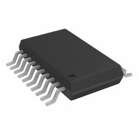
ADCMP564BRQ Analog Devices Inc, ADCMP564BRQ Datasheet - Page 6

ADCMP564BRQ
Manufacturer Part Number
ADCMP564BRQ
Description
HIGH SPEED COMPARATOR
Manufacturer
Analog Devices Inc
Type
with Latchr
Datasheet
1.ADCMP564BRQZ.pdf
(16 pages)
Specifications of ADCMP564BRQ
Rohs Compliant
NO
Number Of Elements
2
Output Type
Complementary, Differential, ECL, Open-Emitter
Voltage - Supply
±4.75 V ~ 5.25 V
Mounting Type
Surface Mount
Package / Case
20-SSOP (0.154", 3.91mm Width)
Lead Free Status / RoHS Status
Contains lead / RoHS non-compliant
For Use With
EVAL-ADCMP564BRQZ - BOARD EVALUATION ADCMP564BRQZ
Lead Free Status / RoHS Status
Contains lead / RoHS non-compliant
ADCMP563/ADCMP564
PIN CONFIGURATIONS AND FUNCTION DESCRIPTIONS
Table 3. Pin Function Descriptions
ADCMP563
16-Lead
QSOP
1
2
3
4
5
6
7
8
9
10
11
–INA
+INA
GND
LEA
LEA
Figure 5. ADCMP563 16-Lead QSOP
V
QA
QA
EE
1
2
3
4
5
6
7
8
Pin Configuration
ADCMP563
(Not to Scale)
TOP VIEW
ADCMP563
16-Lead
LFCSP
15
16
1
2
3
4
5
6
7
8
9
BRQ
Pin No.
16
15
14
13
12
11
10
9
QB
QB
GND
LEB
LEB
V
–INB
+INB
CC
ADCMP564
20-Lead
QSOP
1
2
3
4
5
6
7
8
9
10
11
12
13
14
Mnemonic
GND
QA
QA
GND
LEA
LEA
V
−INA
+INA
HYSA
HYSB
+INB
−INB
V
EE
CC
HYSA
–INA
+INA
GND
GND
LEA
LEA
Figure 6. ADCMP564 20-Lead QSOP
V
QA
QA
EE
10
1
2
3
4
5
6
7
8
9
Function
Analog Ground.
One of Two Complementary Outputs for Channel A. QA is logic high if the
analog voltage at the noninverting input is greater than the analog voltage
at the inverting input (provided the comparator is in compare mode). See
the description of the LEA pin for more information.
One of Two Complementary Outputs for Channel A. QA is logic low if the
analog voltage at the noninverting input is greater than the analog voltage
at the inverting input (provided the comparator is in compare mode). See
the description of the LEA pin for more information.
Analog Ground.
One of Two Complementary Inputs for Channel A Latch Enable. In compare
mode (logic high), the output tracks change at the input of the comparator.
In latch mode (logic low), the output reflects the input state just prior to the
comparator being placed in the latch mode. LEA must be driven in
conjunction with LEA. If left unconnected, the comparator defaults to
compare mode.
One of Two Complementary Inputs for Channel A Latch Enable. In compare
mode (logic low), the output tracks change at the input of the comparator.
In latch mode (logic high), the output reflects the input state just prior to the
comparator being placed in the latch mode. LEA must be driven in
conjunction with LEA. If left unconnected, the comparator defaults to
compare mode.
Negative Supply Terminal.
Inverting Analog Input of the Differential Input Stage for Channel A. The
Inverting A input must be driven in conjunction with the Noninverting A input.
Noninverting Analog Input of the Differential Input Stage for Channel A. The
Noninverting A input must be driven in conjunction with the Inverting A input.
Programmable Hysteresis Input.
Programmable Hysteresis Input.
Noninverting Analog Input of the Differential Input Stage for Channel B. The
Noninverting B input must be driven in conjunction with the Inverting B input.
Inverting Analog Input of the Differential Input Stage for Channel B. The
Inverting B input must be driven in conjunction with the Noninverting B input.
Positive Supply Terminal.
Rev. B | Page 6 of 16
ADCMP564
Pin Configuration
(Not to Scale)
TOP VIEW
BRQ
20
19
18
17
16
15
14
13
12
11
GND
QB
QB
GND
LEB
LEB
V
–INB
+INB
HYSB
CC
GND
LEA
LEA
V
EE
Figure 7. ADCMP563 16-Lead LFCSP
1
2
3
4
–INA +INA +INB –INB
QA QA
16
5
Pin Configuration
ADCMP563
(Not to Scale)
PIN1
TOP VIEW
15
6
BCP
QB
14
7
QB
13
8
12
11
10
9
GND
LEB
LEB
V
CC


