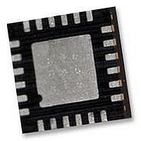
WM8523GEFL/RV Wolfson Microelectronics, WM8523GEFL/RV Datasheet - Page 32

WM8523GEFL/RV
Manufacturer Part Number
WM8523GEFL/RV
Description
IC, DAC, STEREO, 2VRMS, 2CH, 24QFN
Manufacturer
Wolfson Microelectronics
Datasheet
1.WM8523GEFLRV.pdf
(50 pages)
Specifications of WM8523GEFL/RV
Resolution (bits)
24bit
Sampling Rate
192kSPS
Input Channel Type
Serial
Digital Ic Case Style
QFN
No. Of Pins
24
Operating Temperature Range
-40°C To +85°C
Svhc
No SVHC (15-Dec-2010)
Package
RoHS Compliant
Data Interface
I2C, Serial, SPI
Supply Voltage Range - Analogue
2.97V To 3.63V
Rohs Compliant
Yes
WM8523
HARDWARE CONTROL INTERFACE
w
The WM8523 can be controlled in hardware mode or in software modes. In hardware mode, the device
is configured according to logic levels applied to hardware pins.
Hardware control mode is selected by leaving CIFMODE pin open-circuit (high-impedance).
hardware mode is selected, the associated multi-function control pins are defined as described in Table
22.
Table 22 Hardware Control Pin Configuration
DE-EMPHASIS
A digital de-emphasis filter may be applied to the DAC output when the sampling frequency is 44.1kHz.
Operation at 48kHz and 32kHz is also possible, but with an increase in the error from the ideal response.
Details of the de-emphasis filter characteristic for 32kHz, 44.1kHz and 48kHz can be seen in Figure 31 to
Figure 36.
MUTE
In hardware mode, the MUTE
is asserted a softmute is applied to ramp the signal down, with the ramp rate related to the sample rate
as defined in Table 15 on page 30. Once mute is achieved, the ZFLAG is asserted. When the mute is
de-asserted the signal returns to full scale in one step and the ZFLAG is de-asserted.
ZERO DETECT
The zero detect function in hardware mode will assert the ZFLAG pin high when 1024 zero count
samples are input to the digital audio interface. Additionally, the ZFLAG is asserted when the device is
muted using the MUTE
ZFLAG
DEEMPH
AIFMODE0
AIFMODE1
MUTE
¯ ¯ ¯ ¯ ¯
CIFMODE
PIN NAME
PIN NAME
¯ ¯ ¯ ¯ ¯ pin and also until the device comes out of reset.
TSSOP
¯ ¯ ¯ ¯ ¯ pin controls the DAC mute to both left and right channels. When the mute
PIN NUMBER
12
13
14
15
16
7
QFN
24
5
6
7
8
9
Zero Flag Output
0 = Normal operation
1 = Infinite zero detect is triggered or mute is applied
De-emphasis Filter Select
0 = Filter disabled
1 = Filter enabled
Mute Control
0 = Mute
1 = Normal operation
Control Interface Mode
0 = I
1 = SPI Mode
Z = Hardware Mode
AIFMODE1
2
0
0
1
1
C Mode
AIFMODE0
DESCRIPTION
0
1
0
1
16-bit Right Justified
24-bit Right Justified
24-bit Left Justified
PP, Rev 3.0, July 2009
FORMAT
24-bit I
Pre-Production
2
S
When
32


