EVAL-ADT7X10EBZ Analog Devices Inc, EVAL-ADT7X10EBZ Datasheet - Page 3
EVAL-ADT7X10EBZ
Manufacturer Part Number
EVAL-ADT7X10EBZ
Description
Evaluation Board I.c.
Manufacturer
Analog Devices Inc
Specifications of EVAL-ADT7X10EBZ
Sensor Type
Temperature
Sensing Range
-55°C ~ 150°C
Interface
I²C
Sensitivity
±0.5°C
Voltage - Supply
2.7 V ~ 5.5 V
Embedded
No
Utilized Ic / Part
ADT7410
Silicon Manufacturer
Analog Devices
Silicon Core Number
ADT7410
Kit Application Type
Sensing - Temperature
Application Sub Type
Temperature Sensor
Lead Free Status / RoHS Status
Lead free / RoHS Compliant
Other names
EVAL-ADT7410EBZ
EVAL-ADT7410EBZ
EVAL-ADT7410EBZ


Evaluation Board User Guide
EVALUATION BOARD
SETTING UP THE EVALUATION BOARD
Follow these steps to set up the ADT7310/ADT7410 evalu-
ation board:
1.
2.
3.
4.
5.
Install the evaluation software from the evaluation kit CD
before connecting the evaluation board to your computer.
Run the file AD7x10 Evaluation Software Install.exe, and
follow all on-screen installation instructions.
Plug the USB connector from the USB port on your PC into
the mini-USB socket (J3) on the evaluation board. The
power indicator LED on the board should illuminate.
Your computer will automatically associate the evaluation
software with the board. The evaluation software is not
digitally signed. If a message window appears during the
association process, click Continue Anyway.
Ensure that all switches and links are in their default positions;
Switch 3 and Switch 4 should be set to the on position.
Start the ADT7310/ADT7410 evaluation software.
Rev. 0 | Page 3 of 12
EVALUATION BOARD DESCRIPTION
The ADT7310/ADT7410 evaluation board allows you to evaluate
all features of the ADT7310/ADT7410. The board is powered
via the USB connection to the host PC. The evaluation software
allows data to be read from and written to the ADT7310/ADT7410.
The evaluation software should be installed on your PC before
the board is plugged in.
Figure 1 is a block diagram of the ADT7310/ADT7410 evaluation
board, showing all the main components and how they are
connected. Figure 12 and Figure 13 show the silkscreens for the
evaluation board to aid in locating components on the board.
The main components on the board are the ADT7310/ADT7410
high accuracy temperature sensors, U1 and U2.
Also on the main evaluation board is a microcontroller. This
microcontroller sets up and controls the ADT7310/ADT7410
over an SPI or I
to and from the PC.
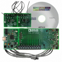
The ADT7310/ADT7410 main evaluation board is powered via
the USB connection. The V
voltage regulator (3.3 V output) before being distributed around
the board. The LEDs illuminate when the board is powered.
The secondary board can be connected to the main board via
Connector J2. There is one ADT7310 and one ADT7410 on the
secondary board. The secondary board can be placed at some
distance from the main board to easily measure the temperature
of interest. There are also LEDs on the secondary board, which
illuminate to indicate that the secondary board is powered.
There are connectors and test points available on all signals of
interest to ensure easy accessibility.
2
C interface and takes care of the USB protocol
DD
signal goes through an ADP3303
UG-047
Related parts for EVAL-ADT7X10EBZ
Image
Part Number
Description
Manufacturer
Datasheet
Request
R


Part Number:
Description:
BOARD EVAL FOR SI270X-A
Manufacturer:
Silicon Laboratories Inc
Datasheet:

Part Number:
Description:
BUCK CONV REF DESIGN KIT IP1201
Manufacturer:
International Rectifier
Datasheet:
Part Number:
Description:
BOARD DEMO SYNC DUAL BUCK CNVTER
Manufacturer:
International Rectifier
Datasheet:
Part Number:
Description:
BOARD DEMO SYNC BUCK CONVETER
Manufacturer:
International Rectifier
Datasheet:

Part Number:
Description:
EVALBOARD/EB Omnidirectional microphone - Analog
Manufacturer:
Analog Devices
Datasheet:
Part Number:
Description:
EVALBOARD/EB Omnidirectional microphone - Analog
Manufacturer:
Analog Devices
Datasheet:


Part Number:
Description:
BOARD EVAL LED DRIVER LT3756
Manufacturer:
Linear Technology
Datasheet:

Part Number:
Description:
BOARD EVAL FOR AD7741/7742
Manufacturer:
Analog Devices Inc
Datasheet:

Part Number:
Description:
±1.7g Dual-Axis IMEMS Accelerometer Evaluation Board
Manufacturer:
Analog Devices Inc
Datasheet:

Part Number:
Description:
IC MULTIPLIER ANALOG 8-SOIC T/R
Manufacturer:
Analog Devices Inc
Datasheet:

Part Number:
Description:
IC ANALOG MULTIPLIER 8-DIP
Manufacturer:
Analog Devices Inc
Datasheet:
Part Number:
Description:
IC ANALOG MULTIPLIER 8-SOIC
Manufacturer:
Analog Devices Inc
Datasheet:
Part Number:
Description:
IC ANALOG MULTIPLIER 8-DIP
Manufacturer:
Analog Devices Inc
Datasheet: