EVAL-ADAU1761Z Analog Devices Inc, EVAL-ADAU1761Z Datasheet - Page 6
EVAL-ADAU1761Z
Manufacturer Part Number
EVAL-ADAU1761Z
Description
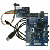
Eval Board For ADAU1761
Manufacturer
Analog Devices Inc
Series
SigmaDSP®r
Specifications of EVAL-ADAU1761Z
Main Purpose
Audio, CODEC
Embedded
Yes, DSP
Utilized Ic / Part
ADAU1761
Primary Attributes
Stereo, 24-Bit, 8 ~ 96 kHz Sampling Rate, GUI Tool
Secondary Attributes
I²C and GPIO Interfaces, 2 Differential and 1 Stereo Single-Ended Analog Inputs and Outputs
Silicon Manufacturer
Analog Devices
Core Architecture
SigmaDSP
Silicon Core Number
ADAU1761
Silicon Family Name
SigmaDSP
Application Sub Type
Audio
Lead Free Status / RoHS Status
Lead free / RoHS Compliant
Available stocks
Company
Part Number
Manufacturer
Quantity
Price
Company:

Part Number:
EVAL-ADAU1761Z
Manufacturer:
Analog Devices Inc
Quantity:
135


EVAL-ADAU1761Z
Table 2. Analog and Digital Audio Connectors
Jack
J4
J6
J19
J20
J21
J22
J23
J24
J25
CLOCKING THE EVALUATION BOARD
The EVAL-ADAU1761Z requires a master clock to operate. The
source of this clock is set by Switch S5 (see Table 3).
Table 3. Master Clock Source Settings
Clock Source
Do not use—function disabled on USBi
MCLK from Header J6
On-board 12.288 MHz clock oscillator (U3)
EXTERNAL DIGITAL AUDIO HEADER
The LRCLK, BCLK, ADC_SDATA, and DAC_SDATA pins of
the ADAU1761 can be connected to external devices with the
5 × 2 Header J6. The pins on the top row of J6 are connected to
ground; the pins on the bottom row are the signals indicated on
the silkscreen.
In SigmaStudio, the digital input channels (Channel 0 to
Channel 7) are accessed in the input cell in Position 2 to
Position 9, as shown in Figure 6. Position 0 and Position 1
are inputs from the ADCs.
DIGITAL MICROPHONE AND JACK DETECTION
INPUT
A pair of digital microphones can be connected to the eval-
uation board on Header J4. The pin connections for J4 are
detailed on the evaluation board silkscreen.
Figure 6. Digital Audio Inputs 0 to 7 in SigmaStudio Input Cell
Function
Stereo digital microphone input
Serial data port input/output
Capless headphone output
Left differential input
Left differential output
Right differential input
Stereo single-ended line output
Stereo single-ended line input
Right differential output
S5 Setting
Up
Middle
Down
Rev. 0 | Page 6 of 12
J7 and J8 set up the routing of signals to the JACKDET/MICIN
pin of the ADAU1761. These jumper settings are shown in
Figure 7, Figure 8, and Figure 9; they are also shown on the PCB
silkscreen. Toggling the jack detection signal can be simulated
by setting up the jack detect function on the ADAU1761 and
then inserting and removing Jumper J8 with J7-B (lower
connection) connected.
I
The I
ADAU1761 communications port. This header connects to the
USBi board (EVAL-ADUSB2), which controls communication
between the evaluation board and SigmaStudio on the PC.
Additionally, a DSP reset line and USB bus power line are
provided. The SigmaStudio hardware configuration for this
setup is shown in Figure 10.
Figure 9. Jumper Settings (J7 and J8) for Jack Detection (High Signal Detected)
Figure 8. Jumper Settings (J7 and J8) for Jack Detection (Low Signal Detected)
2
Figure 7. Jumper Settings (J7 and J8) for Stereo Digital Microphone Input
C COMMUNICATIONS HEADER
Figure 10. Using the EVAL-ADAU1761Z and the USBi with SigmaStudio
2
C communications header, J1, provides an interface to the
J7
J7
J7
J8
J8
J8
Related parts for EVAL-ADAU1761Z
Image
Part Number
Description
Manufacturer
Datasheet
Request
R


Part Number:
Description:
BOARD EVAL FOR SI270X-A
Manufacturer:
Silicon Laboratories Inc
Datasheet:

Part Number:
Description:
BUCK CONV REF DESIGN KIT IP1201
Manufacturer:
International Rectifier
Datasheet:
Part Number:
Description:
BOARD DEMO SYNC DUAL BUCK CNVTER
Manufacturer:
International Rectifier
Datasheet:
Part Number:
Description:
BOARD DEMO SYNC BUCK CONVETER
Manufacturer:
International Rectifier
Datasheet:

Part Number:
Description:
EVALBOARD/EB Omnidirectional microphone - Analog
Manufacturer:
Analog Devices
Datasheet:
Part Number:
Description:
EVALBOARD/EB Omnidirectional microphone - Analog
Manufacturer:
Analog Devices
Datasheet:


Part Number:
Description:
BOARD EVAL LED DRIVER LT3756
Manufacturer:
Linear Technology
Datasheet:

Part Number:
Description:
BOARD EVAL FOR AD7741/7742
Manufacturer:
Analog Devices Inc
Datasheet:

Part Number:
Description:
±1.7g Dual-Axis IMEMS Accelerometer Evaluation Board
Manufacturer:
Analog Devices Inc
Datasheet:

Part Number:
Description:
IC MULTIPLIER ANALOG 8-SOIC T/R
Manufacturer:
Analog Devices Inc
Datasheet:

Part Number:
Description:
IC ANALOG MULTIPLIER 8-DIP
Manufacturer:
Analog Devices Inc
Datasheet:
Part Number:
Description:
IC ANALOG MULTIPLIER 8-SOIC
Manufacturer:
Analog Devices Inc
Datasheet:
Part Number:
Description:
IC ANALOG MULTIPLIER 8-DIP
Manufacturer:
Analog Devices Inc
Datasheet: