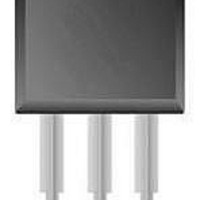
BYV34-500 NXP Semiconductors, BYV34-500 Datasheet - Page 2

BYV34-500
Manufacturer Part Number
BYV34-500
Description
Rectifiers RAIL REC-EPI
Manufacturer
NXP Semiconductors
Specifications of BYV34-500
Product
Ultra Fast Recovery Rectifier
Configuration
Dual Common Cathode
Reverse Voltage
500 V
Forward Voltage Drop
1.35 V
Recovery Time
60 ns
Forward Continuous Current
20 A
Max Surge Current
132 A
Reverse Current Ir
50 uA
Mounting Style
Through Hole
Maximum Operating Temperature
+ 150 C
Minimum Operating Temperature
- 40 C
Package / Case
TO-220AB
Lead Free Status / RoHS Status
Lead free / RoHS Compliant
Other names
BYV34-500,127
Available stocks
Company
Part Number
Manufacturer
Quantity
Price
Company:
Part Number:
BYV34-500
Manufacturer:
PHI
Quantity:
1 250
Company:
Part Number:
BYV34-500
Manufacturer:
FSC
Quantity:
6 000
Company:
Part Number:
BYV34-500
Manufacturer:
NXP
Quantity:
51 000
Part Number:
BYV34-500
Manufacturer:
PHILIPS/飞利浦
Quantity:
20 000
Company:
Part Number:
BYV34-500+127
Manufacturer:
STC
Quantity:
1 260
NXP Semiconductors
FEATURES
• Low forward volt drop
• Fast switching
• Soft recovery characteristic
• High thermal cycling performance
• Low thermal resistance
GENERAL DESCRIPTION
Dual, common cathode, ultra-fast,
epitaxial rectifier diodes intended
for use as output rectifiers in high
frequency switched mode power
supplies.
The BYV34 series is supplied in the
conventional
(TO220AB) package.
LIMITING VALUES
Limiting values in accordance with the Absolute Maximum System (IEC 134).
THERMAL RESISTANCES
1 Neglecting switching and reverse current losses
October 1998
Dual rectifier diodes
ultrafast
SYMBOL PARAMETER
V
V
V
I
I
I
T
T
SYMBOL PARAMETER
R
R
O(AV)
FRM
FSM
stg
j
RRM
RWM
R
th j-hs
th j-a
Peak repetitive reverse voltage
Crest working reverse voltage
Continuous reverse voltage
Average rectified output current square wave; δ = 0.5;
(both diodes conducting)
Repetitive peak forward current t = 25 µs; δ = 0.5;
per diode
Non-repetitive peak forward
current per diode.
Storage temperature
Operating junction temperature
Thermal resistance junction to
heatsink
Thermal resistance junction to
ambient
leaded
SOT78
1
PINNING
SYMBOL
PIN
tab
1
2
3
a1
CONDITIONS
T
T
T
t = 10 ms
t = 8.3 ms
sinusoidal; with reapplied
V
CONDITIONS
per diode
both diodes conducting
in free air.
1
mb
mb
mb
RRM(max)
anode 1
cathode
anode 2
cathode
≤ 138˚C
≤ 115 ˚C
≤ 115 ˚C
DESCRIPTION
k
1
2
a2
3
BYV34
MIN.
-40
QUICK REFERENCE DATA
-
-
-
-
-
-
-
-
SOT78 (TO220AB)
V
R
MIN.
-300
300
300
300
= 300 V/ 400 V/ 500 V
-
-
-
I
V
O(AV)
t
F
rr
MAX.
Product specification
tab
TYP.
-400
400
400
400
132
120
150
150
≤ 1.05 V
≤ 60 ns
20
20
60
-
-
BYV34 series
= 20 A
1 2 3
MAX.
-500
500
500
500
2.4
1.6
-
Rev 1.400
UNIT
UNIT
K/W
K/W
K/W
˚C
˚C
V
V
V
A
A
A
A


