583649-6 TE Connectivity, 583649-6 Datasheet - Page 95
583649-6
Manufacturer Part Number
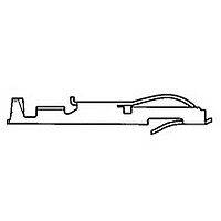
583649-6
Description
TW LF CONTACT LP OF 583649-3
Manufacturer
TE Connectivity
Type
Bifurcated Contactr
Datasheet
1.583649-6.pdf
(96 pages)
Specifications of 583649-6
Number Of Contacts
1POS
Body Orientation
Straight
Contact Plating
Gold Over Nickel
Contact Material
Phosphor Bronze
Termination Method
Crimp
Mounting Style
Cable
Product Height (mm)
3.35mm
Operating Temp Range
-55C to 105C
Pitch (mm)
Not Requiredmm
Current Rating (max)
5A
Contact Resistance Max
10
Rohs Compliant
NO
Product Type
Contact
Termination Method To Wire/cable
Crimp
Wire Insulation Diameter (mm [in])
1.14 – 2.41 [0.045 – 0.095]
Color Code
Violet
Contact Retention In Housing
Crimp Snap-In
Solder Tail Contact Plating
Nickel (30)
Centerline (mm [in])
3.18 [0.125], 3.96 [0.156]
Wire Range (mm [awg])
0.30-0.90² [22-18]
Contact Configuration
Bifurcated
Contact Plating, Mating Area, Material
Gold (30)
Contact Base Material
Phosphor Bronze
Rohs/elv Compliance
Not ELV/RoHS compliant
Lead Free Solder Processes
Not relevant for lead free process
Contact Packaging Method
Loose Piece
Lead Free Status / RoHS Status
Not Compliant


Tooling
.100 x .100 [2.54 x 2.54] Centerline Connectors
.125 x .125 [3.18 x 3.18] Centerline Connectors
Catalog 1654080
Issued 7-03
www.tycoelectronics.com
Positions
Positions
No. of
No. of
Dual
Dual
100
112
124
140
110
115
120
125
140
175
50
80
40
52
56
60
72
84
Applicator
Applicator
266267-4
266267-3
266267-4
266267-5
266267-5
266267-5
266267-4
266267-4
266267-5
313139-1
313139-2
313139-2
313139-2
313139-3
313139-2
313139-2
313139-2
313139-2
T-Bar
T-Bar
Dimensions are in inches and
millimeters unless otherwise
specified. Values in brackets
are metric equivalents.
Removal
265924-4
265924-4
265924-4
265924-4
265924-4
265924-4
265924-4
265924-4
265924-4
Removal
265924-4
265924-6
265924-6
265924-7
265924-4
265924-5
265924-7
265924-5
265924-5
Carrier
Carrier
Tool
Tool
Assembly tooling is not
required except when
using connectors with
ACTION PIN contacts.
ACTION PIN contact
assembly requires an
arbor-style bench tool with a
capacity of 40 lb [178 N] per
contact, a support fixture,
contact applicator, carrier
removal tool and housing
assembly tool.
Card Edge Connectors
(Solder Type, Board-to-Board)
Linear ZIF Connectors
Assembly
Assembly
313136-1
313136-2
313136-3
313136-4
313136-5
313136-1
313136-2
313136-3
313136-4
313136-5
Housing
Housing
Tool
Tool
Dimensions are shown for
reference purposes only.
Specifications subject
to change.
Removal
313256-1
Removal
313256-1
Housing
Housing
Tool
Tool
(Continued)
Typical procedure is to
place a PC board on the
support fixture, insert contact
combs into the printed circuit
board with the contact appli-
cator and seat with the arbor
tool. Next, remove the carrier
strip from the contact combs
with the carrier break-off tool.
Place the housing over the
contacts with the housing
assembly tool, and repeat
the entire process until the
board is complete.
Wing Removal/
Wing Removal/
Replacement
Replacement
266233-1
266233-1
Tool
Tool
USA: 1-800-522-6752
Canada: 1-905-470-4425
Mexico: 01-800-733-8926
C. America: 52-55-5-729-0425
Insertion
266264-1
Insertion
266264-1
Housing
Housing
Tool
Tool
With Housing
With Housing
266235-1
266235-1
Contact Replacement Tools
Contact Replacement Tools
South America: 55-11-3611-1514
Hong Kong: 852-2735-1628
Japan: 81-44-844-8013
UK: 44-141-810-8967
Without Housing
Without Housing
3-265871-2
3-265871-2
95
Related parts for 583649-6
Image
Part Number
Description
Manufacturer
Datasheet
Request
R

Part Number:
Description:
CONT TWIN LEAF
Manufacturer:
TE Connectivity
Datasheet:
Part Number:
Description:
CONT.CRP.SNAP TW.LF.STRIP
Manufacturer:
TE Connectivity
Datasheet:

Part Number:
Description:
CONT.CRP.SNAP TW.LF.STRIP
Manufacturer:
TE Connectivity
Datasheet:

Part Number:
Description:
High Speed / Modular Connectors 30P HEADER ASSY
Manufacturer:
TE Connectivity
Datasheet:

Part Number:
Description:
High Speed / Modular Connectors REC 6X005P R/A LT B-PLANE HS3
Manufacturer:
TE Connectivity
Datasheet:

Part Number:
Description:
High Speed / Modular Connectors 2MM HM RCPT 50P R/A AU
Manufacturer:
TE Connectivity
Datasheet:

Part Number:
Description:
High Speed / Modular Connectors 2MM HM RCPT 50P R/A AU
Manufacturer:
TE Connectivity
Datasheet:


Part Number:
Description:
Manufacturer:
TE Connectivity
Datasheet:


Part Number:
Description:
Manufacturer:
TE Connectivity
Datasheet:

Part Number:
Description:
Manufacturer:
TE Connectivity
Datasheet:

Part Number:
Description:
Manufacturer:
TE Connectivity
Datasheet: