583649-6 TE Connectivity, 583649-6 Datasheet - Page 45
583649-6
Manufacturer Part Number
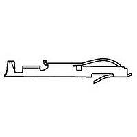
583649-6
Description
TW LF CONTACT LP OF 583649-3
Manufacturer
TE Connectivity
Type
Bifurcated Contactr
Datasheet
1.583649-6.pdf
(96 pages)
Specifications of 583649-6
Number Of Contacts
1POS
Body Orientation
Straight
Contact Plating
Gold Over Nickel
Contact Material
Phosphor Bronze
Termination Method
Crimp
Mounting Style
Cable
Product Height (mm)
3.35mm
Operating Temp Range
-55C to 105C
Pitch (mm)
Not Requiredmm
Current Rating (max)
5A
Contact Resistance Max
10
Rohs Compliant
NO
Product Type
Contact
Termination Method To Wire/cable
Crimp
Wire Insulation Diameter (mm [in])
1.14 – 2.41 [0.045 – 0.095]
Color Code
Violet
Contact Retention In Housing
Crimp Snap-In
Solder Tail Contact Plating
Nickel (30)
Centerline (mm [in])
3.18 [0.125], 3.96 [0.156]
Wire Range (mm [awg])
0.30-0.90² [22-18]
Contact Configuration
Bifurcated
Contact Plating, Mating Area, Material
Gold (30)
Contact Base Material
Phosphor Bronze
Rohs/elv Compliance
Not ELV/RoHS compliant
Lead Free Solder Processes
Not relevant for lead free process
Contact Packaging Method
Loose Piece
Lead Free Status / RoHS Status
Not Compliant


Product Facts
Physical Properties:
Insulation Resistance—
5000 megohms minimum.
Insertion/Withdrawal Force
(Daughter Card)—8 oz./2 oz.
[35.6 N/ 8.9 N] average contact pair using
.0620 [1.57] steel blade.
Insulator Body—Glass filled
thermoplastic, UL rating 94V-O. High
temp. plastic option is available; add suffix
M399 to part number.
Color—Black
Contacts—High strength copper alloy.
Contact Plating—.000050 [0.00127]
nickel underplate with .000030 [0.00076]
gold in the mating area, tin/lead on tails,
.000100 [0.00254] minimum
Electrical Properties:
Operation Voltage—600 VDC
(sea level)
Current Rating—3 Amperes
Initial Contact Resistance—
10 milliohms
Environmental Properties:
Operating Temperature—
-55˚C to +125˚C
Temperature Cycling—
MIL-STD-202 method 107
Vibration—MIL-STD-202 method 204
Related Product Data:
Polarization Key—page 57
Daughter Card Edge Pattern—
page 57
Catalog 1654080
Issued 7-03
www.tycoelectronics.com
Recognized under the
Component Program
of Underwriters
Laboratories Inc.,
File No. E60980
Certified
by Canadian
Standards
Association,
File No. LR49571
[6.35]
.250
[4.57]
.180
Centered Mounting Ear
.125 [3.18] Thru Hole
Dimensions are in inches and
millimeters unless otherwise
specified. Values in brackets
are metric equivalents.
[15.49] Ref.
.610
Card Edge Connectors
(Solder Type, Board-to-Board)
Modified Bellows Connectors .100 x .200 [2.54 x 5.08] and
.100 x .150 [2.54 x 3.81] Right Angle Dip Solder Tails
No Mounting Ears
[3.25]
.128
[9.35]
.368
Dia.
Dim G
Dim K
Dimensions are shown for
reference purposes only.
Specifications subject
to change.
Dim G - Centered Mounting Ear .125 [3.18] Cross Drilled Hole Only
Dim K - Flush Mounting Ear .125 [3.18] Cross Drilled Hole Only
[2.54]
.100
.100
Mounting Styles
[6.35]
.250
[4.57]
.180
A
Centered Mounting Ear
[2.54]
.040±.003
[1.02±.08] Dia.
USA: 1-800-522-6752
Canada: 1-905-470-4425
Mexico: 01-800-733-8926
C. America: 52-55-5-729-0425
.100
.125 [3.18] Cross
Drilled Hole
C
Ref.
Dim E
B
Dim B
[15.49] Ref.
D
.610
[3.56±.25]
.14±.01
SECTION X-X
E
Row to Row Spacing
[15.49] Ref.
.610
South America: 55-11-3611-1514
Hong Kong: 852-2735-1628
Japan: 81-44-844-8013
UK: 44-141-810-8967
[6.35]
.250
[1.37±1.890]
Dim H
.054±.071
ROTATED 90º
SECTION X-X
Flush Mounting Ear
.125 [3.18] Cross
PC Board
Drilled Hole
.025
[.64]
Sq. Typ.
H
45
Related parts for 583649-6
Image
Part Number
Description
Manufacturer
Datasheet
Request
R

Part Number:
Description:
CONT TWIN LEAF
Manufacturer:
TE Connectivity
Datasheet:
Part Number:
Description:
CONT.CRP.SNAP TW.LF.STRIP
Manufacturer:
TE Connectivity
Datasheet:

Part Number:
Description:
CONT.CRP.SNAP TW.LF.STRIP
Manufacturer:
TE Connectivity
Datasheet:

Part Number:
Description:
High Speed / Modular Connectors 30P HEADER ASSY
Manufacturer:
TE Connectivity
Datasheet:

Part Number:
Description:
High Speed / Modular Connectors REC 6X005P R/A LT B-PLANE HS3
Manufacturer:
TE Connectivity
Datasheet:

Part Number:
Description:
High Speed / Modular Connectors 2MM HM RCPT 50P R/A AU
Manufacturer:
TE Connectivity
Datasheet:

Part Number:
Description:
High Speed / Modular Connectors 2MM HM RCPT 50P R/A AU
Manufacturer:
TE Connectivity
Datasheet:


Part Number:
Description:
Manufacturer:
TE Connectivity
Datasheet:


Part Number:
Description:
Manufacturer:
TE Connectivity
Datasheet:

Part Number:
Description:
Manufacturer:
TE Connectivity
Datasheet:

Part Number:
Description:
Manufacturer:
TE Connectivity
Datasheet: