583649-6 TE Connectivity, 583649-6 Datasheet - Page 57
583649-6
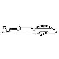
Manufacturer Part Number
583649-6
Description
TW LF CONTACT LP OF 583649-3
Manufacturer
TE Connectivity
Type
Bifurcated Contactr
Datasheet
1.583649-6.pdf
(96 pages)
Specifications of 583649-6
Number Of Contacts
1POS
Body Orientation
Straight
Contact Plating
Gold Over Nickel
Contact Material
Phosphor Bronze
Termination Method
Crimp
Mounting Style
Cable
Product Height (mm)
3.35mm
Operating Temp Range
-55C to 105C
Pitch (mm)
Not Requiredmm
Current Rating (max)
5A
Contact Resistance Max
10
Rohs Compliant
NO
Product Type
Contact
Termination Method To Wire/cable
Crimp
Wire Insulation Diameter (mm [in])
1.14 – 2.41 [0.045 – 0.095]
Color Code
Violet
Contact Retention In Housing
Crimp Snap-In
Solder Tail Contact Plating
Nickel (30)
Centerline (mm [in])
3.18 [0.125], 3.96 [0.156]
Wire Range (mm [awg])
0.30-0.90² [22-18]
Contact Configuration
Bifurcated
Contact Plating, Mating Area, Material
Gold (30)
Contact Base Material
Phosphor Bronze
Rohs/elv Compliance
Not ELV/RoHS compliant
Lead Free Solder Processes
Not relevant for lead free process
Contact Packaging Method
Loose Piece
Lead Free Status / RoHS Status
Not Compliant


Catalog 1654080
Issued 7-03
www.tycoelectronics.com
Description/Application
Tyco Electronics can pro-
vide polarization keys in the
basic configuration shown
on this page. Our Modified
Bellows and Cantilever
Beam Series Card Edge
Connectors use these keys.
The part number and the
connector series for which it
was designed are listed in
the table below.
Per MIL-C-21097E
Dimensions are in inches and
millimeters unless otherwise
specified. Values in brackets
are metric equivalents.
Card Edge Connectors
(Solder Type, Board-to-Board)
Ordering Information
Card Edge Polarization Keys
Card Edge Connectors Recommended Daughter Card Edge Pattern
Daughter Card
* Except MIL-C-21097E 8–4 which is .070 [1.78]
NOTES:
1. Dimensions are in inches
2. Unless otherwise specified, tolerance is ±.005 [0.13 mm] for three place
3. Number of contact fingers shall be the same as the corresponding printed
Acquired Part
decimals.
wiring connector.
Slot Depth
Dim. A
98014-01
98014-01
Contact Spacing
Number
Min.
Non-Accum.
.100 [2.54]
.125 [3.18]
.156 [3.96]
.033
[.84]
Dimensions are shown for
reference purposes only.
Specifications subject
to change.
Break Off Point
Used on Connector
.105* [2.67]
±.005 (.13)
.093 [2.36]
.093 [2.36]
Modified Bellows
Cantilever Beam
Dim A
(Per Applicable Catalog Page)
Series
Dim. B
See Note 3
Contact Spacing
USA: 1-800-522-6752
Canada: 1-905-470-4425
Mexico: 01-800-733-8926
C. America: 52-55-5-729-0425
[4.83]
.19
.052 [1.32]
.052 [1.32]
.094 [2.39]
Dim B
Shown on
Pages
41-56
28-40
45°
[6.10]
.24
South America: 55-11-3611-1514
Hong Kong: 852-2735-1628
Japan: 81-44-844-8013
UK: 44-141-810-8967
Board Thickness
30°
.062 [1.57]
.015
[.38]
57
Related parts for 583649-6
Image
Part Number
Description
Manufacturer
Datasheet
Request
R

Part Number:
Description:
CONT TWIN LEAF
Manufacturer:
TE Connectivity
Datasheet:
Part Number:
Description:
CONT.CRP.SNAP TW.LF.STRIP
Manufacturer:
TE Connectivity
Datasheet:

Part Number:
Description:
CONT.CRP.SNAP TW.LF.STRIP
Manufacturer:
TE Connectivity
Datasheet:

Part Number:
Description:
High Speed / Modular Connectors 30P HEADER ASSY
Manufacturer:
TE Connectivity
Datasheet:

Part Number:
Description:
High Speed / Modular Connectors REC 6X005P R/A LT B-PLANE HS3
Manufacturer:
TE Connectivity
Datasheet:

Part Number:
Description:
High Speed / Modular Connectors 2MM HM RCPT 50P R/A AU
Manufacturer:
TE Connectivity
Datasheet:

Part Number:
Description:
High Speed / Modular Connectors 2MM HM RCPT 50P R/A AU
Manufacturer:
TE Connectivity
Datasheet:


Part Number:
Description:
Manufacturer:
TE Connectivity
Datasheet:


Part Number:
Description:
Manufacturer:
TE Connectivity
Datasheet:

Part Number:
Description:
Manufacturer:
TE Connectivity
Datasheet:

Part Number:
Description:
Manufacturer:
TE Connectivity
Datasheet: