50MT060WHTAPBF Vishay, 50MT060WHTAPBF Datasheet - Page 2
50MT060WHTAPBF
Manufacturer Part Number
50MT060WHTAPBF
Description
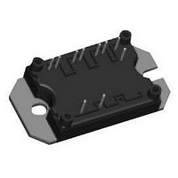
Bridge Rectifiers 600 Volt 50 Amp Half Bridge
Manufacturer
Vishay
Datasheet
1.50MT060WHTAPBF.pdf
(6 pages)
Specifications of 50MT060WHTAPBF
Package / Case
MTP
Maximum Operating Temperature
+ 150 C
Length
63.5 mm
Width
33 mm
Height
16 mm
Mounting Style
Screw
Minimum Operating Temperature
- 40 C
Power Dissipation Pd
658W
Collector Emitter Voltage V(br)ceo
600V
Continuous Collector Current Ic
114A
Leaded Process Compatible
Yes
Collector Emitter Saturation Voltage Vce(sat)
3.2V
Lead Free Status / RoHS Status
Lead free / RoHS Compliant
Lead Free Status / RoHS Status
Lead free / RoHS Compliant, Lead free / RoHS Compliant


50MT060WHTAPbF
Vishay High Power Products
www.vishay.com
2
ELECTRICAL SPECIFICATIONS (T
PARAMETER
Collector to emitter breakdown voltage
Collector to emitter voltage
Gate threshold voltage
Collector to emitter leaking current
Diode forward voltage drop
Gate to emitter leakage current
SWITCHING CHARACTERISTICS (T
PARAMETER
Total gate charge (turn-on)
Gate to emitter charge (turn-on)
Gate to collector charge (turn-on)
Turn-on switching loss
Turn-off switching loss
Total switching loss
Turn-on switching loss
Turn-off switching loss
Total switching loss
Input capacitance
Output capacitance
Reverse transfer capacitance
Diode reverse recovery time
Diode peak reverse current
Diode recovery charge
Diode reverse recovery time
Diode peak reverse current
Diode recovery charge
For technical questions, contact:
SYMBOL
SYMBOL
V
V
V
(BR)CES
C
I
C
C
CE(on)
I
V
Q
Q
E
E
E
E
GE(th)
E
E
Q
Q
CES
GES
Q
t
I
t
I
oes
FM
on
off
on
off
ies
res
rr
rr
rr
rr
ge
gc
ts
ts
rr
rr
g
J
J
(Warp Speed IGBT), 114 A
= 25 °C unless otherwise specified)
"Half Bridge" IGBT MTP
= 25 °C unless otherwise specified)
I
V
V
Internal gate resistors (see electrical diagram)
I
Energy losses include tail and diode reverse
recovery, T
Internal gate resistors (see electrical diagram)
I
Energy losses include tail and diode reverse
recovery, T
V
V
f = 1.0 MHz
V
dI/dt = 200 A/μs
V
dI/dt = 200 A/μs
T
V
V
V
V
I
V
V
I
I
I
V
C
C
C
C
F
F
F
J
CC
GE
GE
CC
CC
CC
GE
GE
GE
GE
GE
GE
GE
= 50 A, V
= 50 A, V
= 100 A, V
= 52 A
= 50 A, V
= 50 A, V
= 0.5 mA
= 125 °C
= 15 V
= 0 V
= 0 V, I
= 15 V, I
= 15 V, I
= 15 V, I
= 0 V, I
= 0 V, I
= ± 20 V
= 400 V
= 30 V
= 200 V, I
= 200 V, I
CC
J
CC
J
C
C
C
GE
GE
TEST CONDITIONS
TEST CONDITIONS
= 25 °C
= 150 °C
C
C
C
GE
= 500 μA
= 600 A
= 600 A, T
C
C
= 480 V, V
= 480 V, V
= 0 V
= 0 V, T
= 50 A
= 100 A
= 50 A, T
= 0 V, T
= 50 A
= 50 A
indmodules@vishay.com
J
J
J
J
= 150 °C
GE
GE
= 25 °C
= 150 °C
= 150 °C
= 15 V, L = 200 μH
= 15 V, L = 200 μH
MIN.
MIN.
600
3
-
-
-
-
-
-
-
-
-
-
-
-
-
-
-
-
-
-
-
-
-
-
-
-
-
-
-
TYP.
7100
TYP.
1.72
1.58
1.49
0.26
1.46
0.73
1.66
2.39
12.7
331
133
510
140
340
137
870
2.3
2.5
1.9
1.2
8.3
44
82
Document Number: 94468
-
-
-
-
-
Revision: 01-Mar-10
MAX.
MAX.
± 250
1132
10.6
14.8
3.15
2.17
1.80
1.68
2.17
385
176
514
153
3.2
0.4
10
52
97
6
-
-
-
-
-
-
-
-
-
-
UNITS
UNITS
mA
nC
mJ
mJ
nC
nC
nA
pF
ns
ns
A
A
V
V
V
Related parts for 50MT060WHTAPBF
Image
Part Number
Description
Manufacturer
Datasheet
Request
R

Part Number:
Description:
IGBT WARP 600V 114A MTP
Manufacturer:
Vishay
Datasheet:
Part Number:
Description:
357-036-542-201 CARDEDGE 36POS DL .156 BLK LOPRO
Manufacturer:
Vishay
Datasheet:
Part Number:
Description:
357-036-542-201 CARDEDGE 36POS DL .156 BLK LOPRO
Manufacturer:
Vishay
Datasheet:
Part Number:
Description:
357-036-542-201 CARDEDGE 36POS DL .156 BLK LOPRO
Manufacturer:
Vishay
Datasheet:
Part Number:
Description:
357-036-542-201 CARDEDGE 36POS DL .156 BLK LOPRO
Manufacturer:
Vishay
Datasheet:
Part Number:
Description:
357-036-542-201 CARDEDGE 36POS DL .156 BLK LOPRO
Manufacturer:
Vishay
Datasheet:
Part Number:
Description:
357-036-542-201 CARDEDGE 36POS DL .156 BLK LOPRO
Manufacturer:
Vishay
Datasheet:
Part Number:
Description:
357-036-542-201 CARDEDGE 36POS DL .156 BLK LOPRO
Manufacturer:
Vishay
Datasheet:
Part Number:
Description:
357-036-542-201 CARDEDGE 36POS DL .156 BLK LOPRO
Manufacturer:
Vishay
Datasheet:
Part Number:
Description:
357-036-542-201 CARDEDGE 36POS DL .156 BLK LOPRO
Manufacturer:
Vishay
Datasheet:
Part Number:
Description:
357-036-542-201 CARDEDGE 36POS DL .156 BLK LOPRO
Manufacturer:
Vishay
Datasheet:
Part Number:
Description:
357-036-542-201 CARDEDGE 36POS DL .156 BLK LOPRO
Manufacturer:
Vishay
Datasheet:
Part Number:
Description:
357-036-542-201 CARDEDGE 36POS DL .156 BLK LOPRO
Manufacturer:
Vishay
Datasheet:
Part Number:
Description:
357-036-542-201 CARDEDGE 36POS DL .156 BLK LOPRO
Manufacturer:
Vishay
Datasheet:
Part Number:
Description:
357-036-542-201 CARDEDGE 36POS DL .156 BLK LOPRO
Manufacturer:
Vishay
Datasheet: