SX-550-1701 Silex Technology, SX-550-1701 Datasheet - Page 19
SX-550-1701
Manufacturer Part Number
SX-550-1701
Description
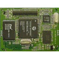
WiFi / 802.11 Modules & Development Tools 802.11a/b/g Bridge Serial Server
Manufacturer
Silex Technology
Datasheet
1.SX-550-6900.pdf
(122 pages)
Specifications of SX-550-1701
Interface Type
UART
Board Size
59.6 mm x 49.1 mm x 14.3 mm
Security
802.1xEAP, PEAP, WEP, WPAPSK, TKIP, WPA2, AES
Operating Voltage
3.3 VDC
Operating Temperature Range
0 C to + 50 C
Lead Free Status / RoHS Status
Lead free / RoHS Compliant


Electrical Characteristics
The power requirements, port pinouts, GPIO characteristics, cable connections and wireless operational
modes are described below.
Power Input
Power to the SX-550 Module and the SX-550-6900 Evaluation Daughtercard is supplied through the
power jack, located at J4, at +5VDC ±10%. Use the included power supply or an equivalent +5VDC
power supply with a minimum of 1 amp capacity.
Power of +3.3VDC ±5% is input to the SX-550 Module via the OEM header, J5.
Power Management
Power for the SX-550 Module is less than 3 watts in normal power mode and peak consumption is less
that 3.3 watts. In low power mode average power is 1.2 watts.
Serial Ports
The two serial ports can be accessed with RS-232 signals, via the DB-9 connectors, or logic signals, via
the 10-pin headers. Note that serial port 2 is dedicated for use as a console port for configuring the SX-
550. Serial Port 2 is always set for operation at 115.2Kbps, 8 bit character size, no parity, and no flow
control.
The two logical serial port headers are located at JP2 and JP6. The serial ports provide four dedicated
signals and three optional signals. The optional signals are configured using jumpers. Table 5 details the
serial port signal descriptions.
All signals are 0 to 3.3 V logic signals.
To use header JP2, disable the RS-232 transceiver, U3, by placing a jumper on both JP8 pins.
To use header JP6, disable the RS-232 transceiver, U6, by placing a jumper on both JP9 pins.
Part Number 40183-101
Pin
1
3
5
7
9
DCD
RXD
TXD
DTR
GND
Signal
Input
Enabled via header
Input
Output
Output
Enabled via header
Table 5 Logical Serial Port Signal Descriptions
Input/Output
Silex SX-550 Developer's Guide
Pin
10
2
4
6
8
DSR
RTS
CTS
No
Connect
3.3V
Signal
Input
Enabled via header
Output
Input
Input/Output
Page 11
Related parts for SX-550-1701
Image
Part Number
Description
Manufacturer
Datasheet
Request
R

Part Number:
Description:
WiFi / 802.11 Modules & Development Tools SS Developers Kit need buy sx-550-1701
Manufacturer:
Silex Technology
Datasheet:

Part Number:
Description:
WiFi / 802.11 Modules & Development Tools 802.11a/b/g Bridge Serial Server
Manufacturer:
Silex Technology
Datasheet:
Part Number:
Description:
WiFi / 802.11 Modules & Development Tools Wired Internal OEM 10/100 Serial Server
Manufacturer:
Silex Technology
Datasheet:

Part Number:
Description:
WiFi / 802.11 Modules & Development Tools Internal OEM SDIO Atheros Crd802.11abg
Manufacturer:
Silex Technology
Datasheet:
Part Number:
Description:
WiFi / 802.11 Development Tools Eval Kit for SX-570/SX-580
Manufacturer:
Silex Technology
Datasheet:

Part Number:
Description:
Networking Modules & Development Tools 10/100 USB Device Server
Manufacturer:
Silex Technology
Datasheet:

Part Number:
Description:
Networking Modules & Development Tools 802.11 b/g Wireless USB Device Server
Manufacturer:
Silex Technology
Datasheet:
Part Number:
Description:
WiFi / 802.11 Modules 802.11a/b/g/n USB dev server, 2 ports
Manufacturer:
Silex Technology
Datasheet:

Part Number:
Description:
WiFi / 802.11 Modules & Development Tools AR6002 Radio Evaluation Kit
Manufacturer:
Silex Technology
Datasheet:
Part Number:
Description:
WiFi / 802.11 Modules & Development Tools 802.11abg SDIO Card Open Source Drivers
Manufacturer:
Silex Technology
Datasheet:
Part Number:
Description:
WiFi / 802.11 Modules WiFi SDIO Radio Card w/cable and antenna
Manufacturer:
Silex Technology
Datasheet:
Part Number:
Description:
WiFi / 802.11 Modules 802.11a/b/g/n USB dev server, 2 ports
Manufacturer:
Silex Technology
Datasheet:
Part Number:
Description:
WiFi / 802.11 Modules WiFi SDIO Radio Card
Manufacturer:
Silex Technology
Datasheet:
Part Number:
Description:
WiFi / 802.11 Modules 802.11a/b/g/n Mini PCI card, 3x3MIMO
Manufacturer:
Silex Technology
Datasheet:
Part Number:
Description:
WiFi / 802.11 Modules 802.11b/g SDIO Surfa ce Mount Mod Sample
Manufacturer:
Silex Technology
Datasheet: