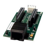
CY3210-28XXX Cypress Semiconductor Corp, CY3210-28XXX Datasheet - Page 11

CY3210-28XXX
Manufacturer Part Number
CY3210-28XXX
Description
EVALUATION POD FOR CY8C28X PSOC
Manufacturer
Cypress Semiconductor Corp
Series
PSoC®r
Datasheet
1.CY3280-28XXX.pdf
(28 pages)
Specifications of CY3210-28XXX
Accessory Type
Emulation Pod
Interface Type
ICE, I2C, RS232, MiniProg,
Operating Supply Voltage
9V, 12 V
Lead Free Status / RoHS Status
Lead free / RoHS Compliant
For Use With/related Products
CY8C28 Family
Lead Free Status / RoHS Status
Lead free / RoHS Compliant, Lead free / RoHS Compliant
2.2
2.2.1
CY3280-28XXX Universal CapSense® Controller Development Kit Guide, Spec. # 001-57457 Rev. **
Table 2-1. Design Features in Universal CapSense Controller (continued)
Using the Board as Factory Programmed
The CY3280-28XXX board is preprogrammed with demonstration firmware. When powered by a
PSoC MiniProg, a CY3240-I2USB Bridge, or an optional external power supply, the LEDs light up
when a finger touches one of the buttons.
These instructions assume that your board has not been reprogrammed from the factory settings. If
it has, and you would like to follow along with this demonstration, follow the instructions in section
2.2.3 Resetting the Board to the Original Factory Programming on page
2.2.1 Powering the
Powering the Board
1. Connect CY3280-SLM Universal CapSense Linear Slider Module Board.
ESD protection circuitry is
not included.
User Module Parameters
set to supplied overlay
thicknesses.
Unused pins are not
routed directly to GND.
0Ω resistors populated
throughout.
Design Features
Board.
Development/evaluation
platform without consis-
tent overlay is inherently
vulnerable to ESD events
Projects optimized for
supplied hardware.
Pins brought out to con-
nector for subsequent
modules or custom
designs.
Universality of the board
enabled by population/
depopulation of 0Ω resis-
tors
Reason for Feature
Direct or air-separated
ESD testing may impair
operation or damage cir-
cuitry. ±2 kV limit on PSoC
pins (see data sheet).
Sensitivity may not be
high enough for very thick
overlays.
Possible noise path.
Solder pads of 0Ω resis-
tors increase parasitic
capacitance.
Impact
12. Start this example with
Include an overlay and
ESD protection circuitry.
Thicker overlays may
require verification of
parameters to ensure
proper operation.
Tie unused sensing traces
directly to ground.
Route traces directly to
sensing elements. Use as
few 0Ω resistors as possi-
ble
Recommended Change
Quick Start
11
[+] Feedback


