56-424-001 Spectrum Control, 56-424-001 Datasheet - Page 95
56-424-001
Manufacturer Part Number
56-424-001
Description
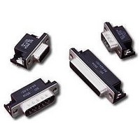
D-Subminiature Connectors 25 PIN FEMALE
Manufacturer
Spectrum Control
Type
Filtered D-Subr
Datasheet
1.56-424-001.pdf
(104 pages)
Specifications of 56-424-001
Number Of Contacts
25POS
Number Of Terminals
25
Plug / Receptacle
SKT
Contact Plating
Gold Over Nickel
Contact Pitch (mm)
2.76mm
Body Orientation
Right Angle
Mounting Style
Through Hole
Number Of Ports
1Port
Number Of Contact Rows
2
Operating Temp Range
-40C to 105C
Termination Method
Solder
Current Rating
5A
Housing Material
Steel
Contact Material
Phosphor Bronze
Product Length (mm)
53.04mm
Product Depth (mm)
19.2mm
Product Height (mm)
12.55mm
Product
Filtered Hoods & Connectors
Number Of Positions / Contacts
25
Shell Plating
Tin
Gender
Female
Mounting Angle
Right
Termination Style
Solder Pin
Operating Temperature Range
- 40 C to + 105 C
Lead Free Status / RoHS Status
Not Compliant
Available stocks
Company
Part Number
Manufacturer
Quantity
Price
Company:

Part Number:
56-424-001
Manufacturer:
API Technologies Corp
Quantity:
457


222
MIL-C-83723, Extended Shell
Series III
All extended shell connectors are manufactured by
adding filters to a standard MIL qualified connector.
The filtering is achieved by extending the connector
with the use of a backshell and placing either planar
or tubular capacitors in the backshell. Spectrum will
always keep the extension to a minimum.
are designed to meet the applicable portions of
MIL-C-83723 and are intermateable with that
specification.
Custom Designs
Due to the versatility provided with this product design,
custom requirements can be readily accommodated.
Consult Spectrum Control for your specific needs.
Materials and Finishes
Shell. . . . . . . . . . . . . . . . . As noted in Ordering Information
Backshell. . . . . . . . . . . . . . . . . . . Copper Alloy, Nickel Plate
Contacts . . . . . . . . . . . . . . . . . . Copper alloy, gold plate per
(For electrical specifications, see page 204.)
Ordering Information
Available connector styles and shell sizes for
this MIL series are shown on the following pages.
Refer to these pages and the information below
to develop your connector part number.
Extended
Shell
Indicator
MIL Series
Indicator
37= MIL-C-83723
Shell Style
A - Wall mount
B - Hermetic box mount
C - Jam nut
D - Hermetic jam nut
E - Straight plug
SPECTRUM CONTROL INC. • 8031 Avonia Rd. • Fairview, PA 16415 • Phone: 814-474-2207 • Fax: 814-474-2208 • Web site: www.spectrumcontrol.com
SPECTRUM CONTROL GmbH • Hansastrasse 6 • 91126 Schwabach, Germany • Phone: (49)-9122-795-0 • Fax: (49)-9122-795-58
. . . . . . . . . . . . . . . . . . . . . . . . . . . . . . . . . . . .
F
These miniature circular filtered connectors
Series III
37
A
Shell Size
8, 10, 12, 14
16, 18, 20, 22
and 24
Finish
R - Aluminum shell,
W - Aluminum, cadmium
Y - Stainless steel,
Contact Arrangement
See next page
24
conductive finish
conductive finish
hermetic seal
MIL-G-45204
R
61
Spectrums Control Advantages
s
filters to customer supplied connectors, saving
time during prototype phase and expediting
system evaluation.
s
are vertically integrated with ceramic capacitors,
enabling us to offer a broad selection of this critical
component and ensuring design versatility and
manufacturing control.
s
large capacitor inventory allow us to quickly provide
a working sample of your filtered connector.
s
we utilize are standards, minimizing our tooling
requirements and providing cost savings and
a shorter lead time.
s
program costs by utilizing our extended shell
connectors for both MIL spec and commercial
grade connectors.
s
a QPL’d connector interface can expedite your
approval process. In addition, we can filter any
series of connectors . . . eliminating concerns
over filter connector availability.
Retrofit existing connectors - We can add
Design flexibility and quality assurance - We
Prototypes - Our EMI filtering expertise and
Economy and turnaround - Most components
MIL and commercial applications - Reduce
Reduce testing and qualification - Use of
Contact/
Termination Type
P-Pin/PC tail
S-Pin/solder cup
B-Socket/PC tail
D-Socket/Solder cup
Alternate
Shell Position
10, 12,
14, 16,
18, 20,
22, 24
Shell
8, 10
Size
All
18
10
P
Polarizing
N (normal)
1, 2, 3, 4
6, 7, 8, 9
10 (Y)
Code
5
N
Filter
Schematic
“1” = “C” feed-thru
“4” = Pi
Filter
Capacitance
Specify by using EIA
codes. Two significant
digits plus number of zeros.
Example:
102 = 1000pF
401 = 400pF
* See table page 204
4
102
Related parts for 56-424-001
Image
Part Number
Description
Manufacturer
Datasheet
Request
R


Part Number:
Description:
USB CONNECTOR, RECEPTACLE, 4POS, THD
Manufacturer:
Spectrum Control
Datasheet:
Part Number:
Description:
USB CONNECTOR, RECEPTACLE, 4POS, THD
Manufacturer:
Spectrum Control
Datasheet:
Part Number:
Description:
USB CONNECTOR, RECEPTACLE, 4POS, THD
Manufacturer:
Spectrum Control
Datasheet:

Part Number:
Description:
Rotary Switch,STRAIGHT,Number Of Positions:3,PC TAIL Terminal,ROTARY SHAFT,PCB Hole Count:12
Manufacturer:
Grayhill Inc
Datasheet:

Part Number:
Description:
Power Line Filters Single Stage
Manufacturer:
Spectrum Control Inc.
Datasheet:
Part Number:
Description:
High Current Single Line Feed-thru Filters
Manufacturer:
Spectrum Control Inc.
Datasheet:
Part Number:
Description:
Switched And Fused Filtered Power Entry Modules
Manufacturer:
Spectrum Control Inc.
Datasheet:
Part Number:
Description:
Surface Mount Emi Filters
Manufacturer:
Spectrum Control Inc.
Datasheet:

Part Number:
Description:
(PSMx Series) Surface Mount EMI Filters
Manufacturer:
Spectrum Control
Datasheet: