56-424-001 Spectrum Control, 56-424-001 Datasheet - Page 75
56-424-001
Manufacturer Part Number
56-424-001
Description
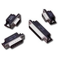
D-Subminiature Connectors 25 PIN FEMALE
Manufacturer
Spectrum Control
Type
Filtered D-Subr
Datasheet
1.56-424-001.pdf
(104 pages)
Specifications of 56-424-001
Number Of Contacts
25POS
Number Of Terminals
25
Plug / Receptacle
SKT
Contact Plating
Gold Over Nickel
Contact Pitch (mm)
2.76mm
Body Orientation
Right Angle
Mounting Style
Through Hole
Number Of Ports
1Port
Number Of Contact Rows
2
Operating Temp Range
-40C to 105C
Termination Method
Solder
Current Rating
5A
Housing Material
Steel
Contact Material
Phosphor Bronze
Product Length (mm)
53.04mm
Product Depth (mm)
19.2mm
Product Height (mm)
12.55mm
Product
Filtered Hoods & Connectors
Number Of Positions / Contacts
25
Shell Plating
Tin
Gender
Female
Mounting Angle
Right
Termination Style
Solder Pin
Operating Temperature Range
- 40 C to + 105 C
Lead Free Status / RoHS Status
Not Compliant
Available stocks
Company
Part Number
Manufacturer
Quantity
Price
Company:

Part Number:
56-424-001
Manufacturer:
API Technologies Corp
Quantity:
457


202
Board & Panel Cutouts
Printed Circuit
Vertical Board Mount (standard density)
Board Layout (Pin and Socket Contact) for Standard D-Sub Connectors
Panel Cutouts (Front or Rear Mounting)
for Standard and Hi-Density D-Sub Connectors
Dimensions in inches (mm)
SPECTRUM CONTROL INC. • 8031 Avonia Rd. • Fairview, PA 16415 • Phone: 814-474-2207 • Fax: 814-474-2208 • Web site: www.spectrumcontrol.com
SPECTRUM CONTROL GmbH • Hansastrasse 6 • 91126 Schwabach, Germany • Phone: (49)-9122-795-0 • Fax: (49)-9122-795-58
15 (1)
25 (2)
37 (3)
50 (4)
Shell
Size
9 (0)
15 (1)
25 (2)
37 (3)
50 (4)
Shell
Size
9 (0)
(24.99)
(33.32)
(47.04)
(63.50)
(61.11)
±.015
1.312
1.852
2.500
2.406
(.38)
.984
A
E
D
(25.00)
(33.32)
(47.04)
(63.50)
(61.11)
1.312
1.852
2.500
2.406
.984
A
J
(12.49)
(16.66)
(23.52)
(31.75)
(30.55)
±.015
1.250
1.203
.492
.656
(.38)
.926
B
C
A
1.308 = 12 x .109
1.962 = 18 x .109
1.744 = 16 x .109
B
.436 = 4 x .109
.763 = 7 x .109
(11.07) (2.77)
(19.38) (2.77)
(33.22) (2.77)
(49.83) (2.77)
(44.30) (2.77)
2 rows
B
(19.74)
(28.07)
(41.78)
(58.24)
(55.63)
±.015
1.105
1.645
2.293
2.190
(.38)
.777
C
G
I
1.199 = 11 x .109
1.853 = 17 x .109
1.635 = 15 x .109
(14.03)
(20.89)
(29.12)
(27.81)
±.015
(9.87)
1.146
1.095
(.38)
.388
.552
.327 = 3 x .109
.654 = 6 x .109
.822
(16.61) (2.77)
(30.45) (2.77)
(47.07) (2.77)
(41.35) (2.77)
(8.31) (2.77)
D
F
1 row
C
(11.18)
(11.18)
(11.18)
(11.18)
(13.97)
H
±.003
.440
.440
.440
.440
.550
(.08)
E
(12.50)
(16.66)
(23.52)
(31.75)
(30.56)
1.250
1.203
(14.99)
.492
.656
.926
±.005
(5.59)
(5.59)
(5.59)
(5.59)
(6.98)
(.13)
.220
.220
.220
.220
.275
.590
D
F
(8.00)
.315
(2.77)
.109
±.002
Printed Circuit
Right Angle Mount (standard density)
(3.81)
(3.81)
(3.81)
(3.81)
(3.81)
.150
.150
.150
.150
.150
(.05)
E
G
(3.18 Dia.)
.125 Dia.
Front
Mounting
Panel Cutouts
(2.84)
2 holes
.112
F
D
E
Front of Flange
J
.056 (1.42)
.275 (6.99)
Rt Angle
2 rows
Mount
Mount
0.112
1 row
PCB
PCB
0.00
G
G
C
B
A
Panel
C
A
(3.18)
.125
H
D
B
Rear
Mounting
(Dia.)
10°
(1.14)
I
.045
I
F
F
E
(1.37)
.054
Panel
G
J
H
Related parts for 56-424-001
Image
Part Number
Description
Manufacturer
Datasheet
Request
R


Part Number:
Description:
USB CONNECTOR, RECEPTACLE, 4POS, THD
Manufacturer:
Spectrum Control
Datasheet:
Part Number:
Description:
USB CONNECTOR, RECEPTACLE, 4POS, THD
Manufacturer:
Spectrum Control
Datasheet:
Part Number:
Description:
USB CONNECTOR, RECEPTACLE, 4POS, THD
Manufacturer:
Spectrum Control
Datasheet:

Part Number:
Description:
Rotary Switch,STRAIGHT,Number Of Positions:3,PC TAIL Terminal,ROTARY SHAFT,PCB Hole Count:12
Manufacturer:
Grayhill Inc
Datasheet:

Part Number:
Description:
Power Line Filters Single Stage
Manufacturer:
Spectrum Control Inc.
Datasheet:
Part Number:
Description:
High Current Single Line Feed-thru Filters
Manufacturer:
Spectrum Control Inc.
Datasheet:
Part Number:
Description:
Switched And Fused Filtered Power Entry Modules
Manufacturer:
Spectrum Control Inc.
Datasheet:
Part Number:
Description:
Surface Mount Emi Filters
Manufacturer:
Spectrum Control Inc.
Datasheet:

Part Number:
Description:
(PSMx Series) Surface Mount EMI Filters
Manufacturer:
Spectrum Control
Datasheet: